Products:
The Primary Arms PLATINUM Series (PLx5) 6-30X56 First Focal Plane Scope is designed from the ground up with uncompromised craftsmanship and optical clarity in mind. Engineered and fully manufactured in Japan for durability and reliability, this scope is capable of handling heavy recoil and abuse. It is fast at 6X and extremely accurate at 30X, remaining true at all magnifications due to its first focal plane configuration.
The ACSS® Apollo™ 6.5CR/.224V reticle virtually eliminates the need for cumbersome mathematics and turret adjustments by providing an intelligent ballistic holdover system for 6.5 Creedmoor and .224 Valkyrie cartridges. Combined with the enhanced glass clarity and high magnification of the 6-30×56 FFP scope, Apollo enables users to quickly and precisely range estimate targets exceeding 1,000 yards distance, and then engage them with confidence.
ACHIEVING A CLEAR RETICLE PICTURE
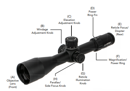
Your PLATINUM Series (PLx5) 6-30X56 FFP scope comes with an adjustable Diopter Ring (D) that must be set to match your eye. Located at the rear of the eyepiece, it is marked simply [+ 0 -]. The diopter ring changes the focus of the reticle as you see it inside the scope. It does not change the focus of objects that you look at through the scope. Setting the diopter is a critical first step to successful precision shooting. You can set the diopter before you have even mounted the scope in its rings.
- Turn the Magnification / Power Ring (E) to a high magnification setting, beyond 15x, and point the scope at a bright, featureless background such as blue sky or a blank white wall.
- Turn the Parallax / Side Focus Knob (G) to infinity [∞].
- With your head in position behind the scope, look at the wall or sky instead. If you look through prescription glasses when shooting, wear them now too. After 5 or 6 seconds, close your eyes.
- Now open your eye, glance through the scope and immediately see if the reticle is sharp or blurry. If you notice that the reticle seems blurry at first and then suddenly sharpens, your eyes have focused on the reticle itself instead of looking through the scope. You must adjust the diopter ring (D) and try again.
- If the reticle was blurry, turn the diopter ring (D) and repeat the process again. The process will take multiple adjustments. Each time you repeat the process, ask yourself if the reticle was sharper or more blurry than before. The final adjustments may be very fine. If your eyes get watery or tired, walk away for a bit and come back to this later.
- Once the reticle appears sharp as soon as you glance through the scope, the diopter is set for your eyes. Everyone’s eyes are slightly different, so the ideal adjustment changes from person to person. Many shooters will mark their correct diopter position with a little dab of paint or fingernail polish next to the 0 mark, in case the ring gets turned accidentally later on. Others will apply electrical tape around the diameter of the ring to hold it in place.
This is a one-time adjustment. Reticle details may appear small when not looking at medium or long range targets, especially at low magnification. Shooting at those ranges is best done from a well-supported position using a bipod or sandbags.
ADJUSTING PARALLAX
The Parallax/Side Focus Knob (G) is located on the left side of the scope, marked with ranges from 35 yards to infinity. Although it is often referred to as a “side focus” knob, parallax and focus are not the same thing. Parallax error occurs when the target’s image and the reticle are not aligned on the same focal plane inside the scope. To visualize this, pick a picture on the wall of a room as your “target”, and stick your thumb up in front of it like you are a hitch-hiker. Your thumb represents the reticle of the scope. Closing one eye and using your thumb to “aim” at the picture on
the wall, you will notice that moving your head around changes where your thumb appears to be aimed. This is because your thumb is not located in the same focal plane as the picture on the wall. Any slight change in your head position will change your point of aim, and your point of impact. Adjusting the Parallax/Side Focus Knob (G) eliminates parallax error at different ranges by bringing the reticle into the same focal plane as the target, like having a friend place their thumb directly against the picture on the wall. Parallax error is most noticeable at high magnifications.
Adjustment is much easier with your rifle secured by sandbags or a bipod.
- Turn the Parallax/Side Focus Knob (G) until the target appears to be in focus. This will get you close to the correct adjustment.
- Looking through the scope at the target, move your head just slightly from side to side. If you lose the sight picture you are moving too much. Go slowly, and see if the reticle appears to move relative to your target. A target that appears to be floating around the reticle as you move your head indicates parallax error.
- If the target appears to move in the opposite direction of your head, turn the Parallax/Side Focus Knob (G) counterclockwise. If the target appears to move in the same direction as your head, turn the Parallax/Side Focus Knob (G) clockwise. These adjustments are very small. Move the Parallax/Side Focus Knob (G) just a little bit at a time and re-check.
- Once the reticle and target hold their positions as you move your head from side to side, parallax error is eliminated for targets at this range. Normally this adjustment will also keep the target nicely in focus. However, to gain the most consistent hits on target, it is more important to eliminate parallax error than to have the target perfectly in focus.
RETICLE ILLUMINATION
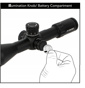
The Reticle Illumination Knob (F) on the left side of the scope is marked with numbers of increasing brightness from 1 to 11. Between each number is an OFF setting. The cap unscrews counter-clockwise, holding a CR2032 battery with the positive (+) side facing towards the cap. Reticle illumination is most useful in low light situations like sunrise and sunset, or indoors. The lowest two settings are compatible with night vision devices and cannot be seen by the naked eye. Reticle “bleed out”, abnormalities and small imperfections may be visible when viewed indoors or in low
light conditions at the brightest settings. This is a normal result of the reticle etching process. Abnormalities at these settings will not be visible when viewed in daylight conditions. Using the brightest settings in low light situations will overpower your eye’s ability to see the target and make the reticle appear distorted. The right amount of illumination creates a clear contrast between the reticle and your intended target, without straining the eye.
ESTABLISHING ZERO
Using a bipod or sandbags, preferably on a bench or in the prone position, turn the Power Ring (E) to a high magnification to see your target as easily as possible. Dial in point of impact to coincide with the tip of the chevron. When sighting in your rifle, if your shots are hitting low, turn the Elevation Knob (C) counterclockwise to bring the point of impact up. If your shots are hitting to the left, turn the Windage Knob (B) counterclockwise to bring the point of impact right.
SETTING THE RETURN TO ZERO SYSTEM
The return to zero system mechanically prevents the Elevation Knob (C) from dialing below a point the user chooses. When shooting at extended ranges where the elevation turret might be hundreds of clicks away from zero, simply spin the Elevation Knob (C) back down without counting clicks to stop at the rifle’s original zero. This saves precious time so you can begin counting clicks back up to the next firing solution more quickly or transition to using the holdovers built into the ACSS Apollo 6.5CR/.224V reticle.
Before Zeroing Your Rifle
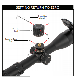
Loosen the 3 set screws positioned around the Elevation Knob (C) using the included 1.5mm Allen wrench. The set screws do not need to be entirely removed, just back them out enough to release all tension against the central shaft. Remove the knob by pulling it straight up. Loosen the three set screws holding the black metal return-tozero ring in position ring in position around the central shaft and remove it by pulling straight up. Replace the Elevation Knob (C) on the central shaft by pressing straight down, and secure it using its 3 set screws. Do not overtighten these tiny set screws!
Zero Your Rifle
Zero your rifle at the desired distance. The position of the numbers on the elevation knob is totally irrelevant at this stage; just get the point of aim and point of impact to coincide at the distance you have chosen (traditionally 100 yards).
After Zeroing Your Rifle
Remove the Elevation Knob (C) as before by loosening the 3 set screws and pulling straight up. Replace the return-to-zero ring on the central shaft as before and turn it clockwise until it stops. You can see two tiny protruding screws touching each other between the return-to-zero ring and the turret base. With the return-to-zero ring in this position, secure it in place using its 3 set screws. Now replace the knob by pressing it straight down on the central shaft, being careful to align the “0” marking on the knob with the centerline mark on the scope body. Secure the Elevation Knob (C) using its 3 set screws. Remember, do not over-torque them! Now the zero is marked “0” on the Elevation Knob (C) and the return-to-zero ring will physically halt the central shaft from turning past that point.
You can also reset zero on the Windage Adjustment Knob (B) similarly, by loosening the set screws, pulling the external knob straight off, and replacing it with the “0” aligned with the centerline mark on the scope body. The Windage Adjustment Knob (B) does not offer a return-to-zero feature.
THE ACSS APOLLO 6.5CR/.224V RETICLE
Apollo is a dedicated 6.5 Creedmoor & .224 Valkyrie specific reticle that features easy to use bullet drop compensation and wind holds out to 1,000 yards. Overall, the reticle extends 10 MIL up, left, and right of the center chevron aiming point. Large hash marks are found in 1.0 MIL increments, with smaller marks between them at 0.5 MIL increments.
The Chevron Tip
ACSS Apollo uses a chevron as the center aiming point of the reticle. Adjust your Windage (B) and Elevation (C) knob positions so that the point of impact coincides with the tip of the chevron. Using the chevron tip allows for an infinitely small point of aim that never covers up the part of the target you want to hit, giving the chevron tip a precision advantage over traditional crosshairs or a center aiming dot.
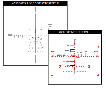
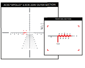
The ACSS Apollo Center Section
The chevron measures just 0.1 MIL down from center and 0.1 MIL to the left and right of center. Thus, the outer tips of the chevron legs are located 0.1 MIL from center, and 0.2 MIL apart from each other. To the left and right of center, boxes are located at 0.2 MIL intervals with a slightly larger rectangle at 1.0 MIL from center for easy navigation. Small dots (0.05 MIL wide) are spaced at 0.2 MIL intervals above and below center for a total of 1.0 MIL distance.
BALLISTICS CHART FOR 6-30X56MM FFP WITH ACSS APOLLO 6.5CR/.224 RETICLE
Instructions for using the ballistics chart:
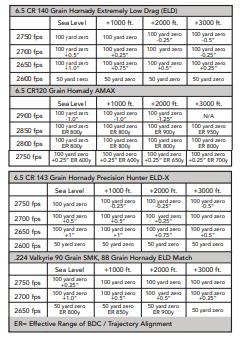
Find your caliber and bullet type. Match up your rifle’s muzzle velocity with your altitude above sea level to find the proper zero distance and offset. Plus (+) and minus (-) numbers indicate desired bullet impact in inches above or below the point of aim during initial zeroing. The popular 6.5 Creedmoor bullet types and two .224 Valkyrie bullet types are shown in the chart.
ER stands for Effective Range of Apollo’s BDC marks. Beyond the ER distance, bullet flight diverges from the BDC markings by 0.5 MIL or more. While hits are certainly possible on larger targets, precision shooting at small targets beyond the ER range is more difficult. After initial sight-in we recommend fine tuning point of impact at distances of 400-600 yards to maximize precision throughout the BDC.
Example: A 6.5 Creedmoor shooter using 140 grain Hornady ELD bullets at 2650 fps, at 2000 feet above sea level, needs to sight in 0.5” high at 100 yards.
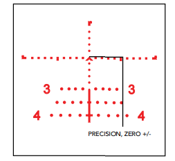
The ACSS Apollo Outer Section
At 2 MIL distance left/right from center, the solid crosshair line begins, using alternating upper and lower marks forming a MIL ranging section. These can be used to range targets using extremely fine 0.1 MIL increments. At 3.0 MIL from center, the 0.5 MIL hash marks begin.
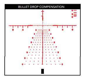
BULLET DROP COMPENSATION & WIND HOLDS
Below center, Apollo features a 6.5 Creedmoor & .224 Valkyrie specific bullet drop compensation ladder. Sighting in Apollo so that your rounds impact at the tip of the chevron at 100 yards, hold midway between the 2nd and 3rd dots underneath the chevron for 200 yards. The BDC begins at 300 yards. Hash marks located at increasing 50-yard intervals indicate bullet drop all the way to 1,000 yards, with numbers labeling every 100 yard increase. After determining the correct range to your target, simply aim using the mark that coincides with that range. The hash marks can be subdivided to make even more precise shots on targets at ranges in between those 50 yard increments. For example, if a target is located 475 yards away, aim using a point halfway between the 450 and 500 yard hash marks.
Wind holds are indicated by dots extending to the left and right of the BDC. They are calculated to represent the distance that crosswinds of 5, 10, 15, and 20 mph will push the bullet left or right. For a wind pushing left to right, use the dots on the right side of the BDC. For a wind pushing right to left, use the dots on the left side of the BDC. For example, if the target is located 700 yards away and a 10-mph wind is crossing from left to right, navigate to the “7” line and use the second dots to the right as your point of aim.
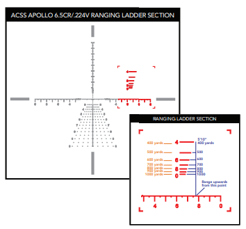
RANGING LADDER
Located high and right of center is the ranging ladder. Vertical ranging is calibrated for a 5’10” tall target. Looking through the scope at the target, line up the bottom of the target with the horizontal crosshair. The line that coincides with the top of the target indicates the distance to the target. For example, if the top of the target touches the line with a “4” next to it, the target is 400 yards distant. The ranging lines may be used as reference points to make more precise, yet quick ranging determinations. For example, a 5’10” target with its top midway between the “4” line and the “5” line will be approximately 450 yards away.
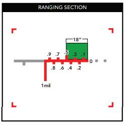
Horizontal ranging is calibrated for an 18” wide target. Simply line up the target’s width with the appropriate line to determine range to target. For example, an 18” wide target that appears to be the same width as the ranging line with a “6” next to it will be 600 yards away. This method is useful when the target’s height is partially obscured, as with a target in tall grass.
HOW TO RANGE ESTIMATE USING MILs
There are two common systems of measurement in the optics world: MOA and MIL. MOA reticles using Minute of Angle subtensions, which equal 1.047” at 100yds and usually adjust in .25 MOA increments. MIL reticles use Milliradian subtensions, which equal 3.6” at 100 yards and usually adjust in .1 MIL increments. The ACSS Apollo 6.5CR/.224V reticle utilizes MILs with a first focal plane design, so your scope’s MILs are accurate subtensions at any magnification power.
A Milliradian, by definition, is an angular measurement equaling 1/1000th the distance between the observer and the target. Simply put, 1 MIL represents 1 yard at 1000-yard distance. This ratio is true across all units, so 1 MIL equals 1 foot at 1000-foot distance, and 1 MIL equals 1 meter at 1000-meter distance. Because MILs are an angular measurement, MIL sizes scale with distance. When observing a target 500 yards away, 1 MIL is equal to 0.5yd. When observing a target 200 yards away, 1 MIL is equal to 0.2yd. This is the basis of MIL-based ranging.
MIL ranging combines size estimation and simple math to deliver incredibly accurate range estimation. Many estimates can be done completely within one’s head without the need for a calculator. Once you memorize the steps, you can quickly measure targets at any range with precision.
Here’s an example of a ranging process:
You see a window at a distance, and you know that window is 18” tall (or 0.5yd). This is your starting point.
Once you have an estimated size of target, find the size of the target in MILs by using your MIL grid for comparison. Because you’re using a first focal plane scope, you can perform this estimate at any magnification, as your MIL subtensions are always accurate. In this example, you measure the window to be 1 MIL tall.
Once you have both the actual target size estimate and the MIL size estimate, the math is easy:
Target Distance in Yards = Target Size in Yards * 1000 / Target MIL Measurement
For the window, this math equals: 0.5yd * 1000 / 1 = 500yd. The window is 500 yards away.
The same formula can be used for meters. Simply use the target size in meters to receive a meters-based distance.
If you want to use target size in inches but still want range in yards, the math is harder, as you will have to convert between units. The easiest method is dividing 1000 by 36(in/yd) for your new constant. The resulting number is 27.8, which replaces 1000 in the in-to-yd MIL formula.
Target Distance in Yards = Target Size in Inches * 27.8 / Target MIL Measurement
While this math is harder, it returns the same answer. For the window, this math equals:
18” * 27.8 / 1 = 500yd. The window is still 500 yards away. Inches are best used when estimating the size for irregular shapes that cannot be easily expressed in yards or meters
LENS CARE
Please do not use any organic solvent such as alcohol or acetone on your scope. First, blow dust or any foreign objects off of the lens. Then, use a soft cotton or microfiber lens cloth to clean any fingerprints or smears off the lens. Alternatively, you may use a piece of professional lens paper for further cleaning, if necessary.
WARNING: Always ensure your firearm is unloaded (chamber empty and magazine removed) before installing optics or accessories.
WARNING: Improper installation of firearm parts or accessories may result in death or serious personal injury. If you are not properly trained in the installation of these parts, have them installed by a gunsmith or armorer.
REMEMBER: THE FOUR RULES OF FIREARMS SAFETY
- Treat every firearm as if it were loaded
- Never let your muzzle cover anything you are not willing to destroy
- Keep your finger off the trigger until your sights are on target
- Be sure of your target and what is behind it