Products:
- Levenhuk Skyline Pro 80 Mak telescope
- Levenhuk Skyline Pro 90 Mak
- Levenhuk Skyline Pro 105 Mak
- Levenhuk Skyline Pro 127 Mak

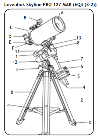
- Dust cap (not shown, remove before viewing)
- Red dot finder
- Focuser lock screw
- Eyepiece
- Diagonal mirror
- Focusing knob
- Dec. slow-motion control
- R.A. slow-motion control
- Latitude adjustment T-bolt
- Azimuth adjustment knob
- Counterweight
- Counterweight lock screw
- Counterweight rod
- R.A. axis scale
- Dec. axis scale
- Dec. lock knob
- R.A. lock knob
- Polarscope
- Dec. setting circle
- Accessory tray
- Tripod leg
- Height adjustment clamp

- Scope
- Azimuth adjustment knob
- Altitude adjustment knob
- Battery compartment cover
- Brightness control

- R.A. adjustment
- Latitude adjustment
- Azimuth adjustment
- R.A. scale
- Dec. adjustment
- R.A. fine adjustment
- Dec. fine adjustment
- Eyepiece
- Barlow lens
- Diagonal mirror

- Big Dipper
- Little Dipper
- Polaris
- NCP
- Cassiopeia
- β Crucis

- R.A. lock knob
- R.A. settling circle
- Arrow

- Zenith
- Meridian
- Latitude
- Nadir
- N E S W
- Right Ascension
- Meridian line
- Plane of Celestial Equator
- Plane of local horizon
- Apparent movement of stars
- Polaris
- Mount aligned on North Celestial Pole
- Object you are viewing
- Declination
- Focuser
- Eyepiece holder
- Extender
- T-adapter
- Camera
CAUTION! Never look directly at the Sun – even for an instant – through your telescope or finderscope without a professionally made solar filter that completely covers the front of the instrument, or permanent eye damage may result. To avoid damage to the internal parts of your telescope, make sure the front end of the finderscope is covered with aluminum foil or another non-transparent material. Children should use the telescope under adult supervision only.
All parts of the telescope will arrive in one box. Be careful when unpacking it. We recommend keeping the original shipping containers. In the event that the telescope needs to be shipped to another location, having the proper shipping containers will help ensure that your telescope survives the journey intact. Make sure all the parts are present in the packaging. Be sure to check the box carefully, as some parts are small. No tools are needed other than those provided. All screws should be tightened securely to eliminate flexing and wobbling, but be careful not to overtighten them, as that may strip the threads. During assembly (and anytime, for that matter), do not touch the surfaces of the optical elements with your fingers. The optical surfaces have delicate coatings on them that can easily be damaged if touched. Never remove lenses and mirrors from their housing, or the product warranty will be null and void.
Telescope assembly
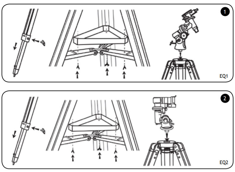
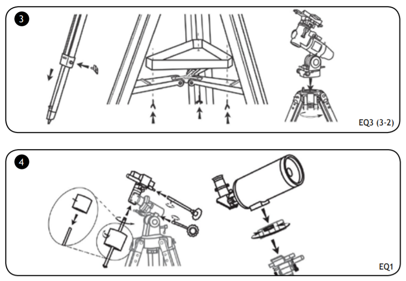
- Slowly loosen the tripod locking knobs and gently pull out the lower section of each tripod leg. (1, 2, 3) Tighten the locking knobs to hold the legs in place.
- Spread the tripod legs apart and stand the tripod upright. Adjust the height of each tripod leg until the tripod head is properly leveled.
- Place the accessory tray on top of the bracket, and lock it in place with thumbscrews.
- Attach the equatorial mount to the tripod head. Lock the mount in place with thumbscrews. (1, 2, 3)
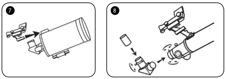
- Attach a counterweight to the counterweight rod. Screw the counterweight rod into the threaded hole on the end of the declination shaft. Tighten the counterweight thumbscrew.
- Attach slow-motion controls to worm gear mechanisms and lock them in place. It is recommended to use the longer slow-motion control for the Dec. axis, and the shorter one for the R.A. axis.
- Attach the 1/4”-20 adapter to the optical tube by rotating the black-head thumbscrew.
- Attach the optical tube to the mount and lock it in place with two locking screws. (4, 5, 6)
Red Dot Finderscope
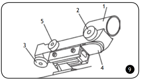
- Insert the finderscope bracket into a holder on the telescope tube and lock it in place with a thumbscrew. (7)
Eyepiece assembly
- Unthread the thumbscrews on the focuser tube.
- Insert the diagonal mirror into the focuser tube and secure it by retightening the thumbscrews.
- Unthread the thumbscrews on the diagonal mirror.
- Insert the desired eyepiece into the diagonal mirror and secure it by retightening the thumbscrews. (8)
Using the red dot finder
The red dot finder is a zero magnification pointing tool that uses a coated glass window to superimpose the image of a small red dot onto the night sky. The red dot finder is equipped with a variable brightness control, azimuth adjustment knob, and altitude adjustment knob. The finder is powered by a 3-volt lithium battery located underneath at the front. To use the red dot finder, simply look through the sight tube and move your telescope until the red dot overlaps the object. Make sure to keep both eyes open when sighting. (9)
Like all finderscopes, the red dot finder must be properly aligned with the telescope before use. This is a simple process using the azimuth and altitude adjustment knobs.
- Open the battery compartment by pulling down the cover and remove the plastic shipping cover over the battery.
- Turn on the red dot finder by rotating the variable brightness control clockwise until you hear a click. Continue rotating the control knob to increase the brightness level.
- Insert a low power eyepiece into the focuser. Locate a bright object and aim the telescope so that the object is in the center of the field of view.
- With both eyes open, look through the sight tube at the object. If the red dot overlaps the object, your red dot finder is perfectly aligned. If not, turn its azimuth and altitude adjustment knob until the red dot overlaps the object.
Balancing the telescope
A telescope should be balanced before each observing session. Balancing reduces stress on the telescope mount and allows precise slow-motion movements. A balanced telescope is especially crucial when using the optional clock drive for astrophotography. The telescope should be balanced after all accessories (eyepiece, camera, etc.) have been attached. Before balancing your telescope, make sure that your tripod is balanced and on a stable surface. For photography, point the telescope in the direction you will be taking photos before performing the balancing steps.
R.A. Balancing
- For best results, adjust the latitude of the mount to between 15° and 30° if possible, by using the latitude adjustment T-bolt
- Slowly unlock the R.A. and Dec. lock knobs. Rotate the telescope until both the optical tube and the counterweight rod are horizontal to the ground, and the telescope tube is to the side of the mount.
- Tighten the Dec. lock knob.
- Move the counterweights along the counterweight rod until the telescope is balanced and remains stationary when released.
- Tighten the counterweight screws to secure the counterweights.
Dec. Balancing
All accessories should be attached to the telescope before balancing around the declination axis. The R.A. balancing should be done before proceeding with Dec. balancing.
- For best results, adjust the latitude of the mount to between 60° and 75° if possible.
- Release the R.A. lock knob and rotate around the R.A. axis so that the counterweight rod is in a horizontal position. Tighten the R.A. lock knob.
- Unlock the Dec. lock knob and rotate the telescope tube until it is parallel to the ground.
- Slowly release the telescope and determine in which direction it rotates. Loosen the telescope ring clamps and slide the telescope tube forward or backward between the rings until it is balanced.
- Once the telescope no longer rotates from its parallel starting position, retighten the tube rings and the Dec. lock knob. Reset the latitude to your local latitude.
Operating the mount
The mount has controls for both conventional latitude and azimuth directions of motion. These two adjustments are suggested for large direction changes and for terrestrial viewing. To adjust azimuth, loosen the big knob under the mount base and rotate the mount head about the azimuth axis. Use the latitude adjustment T-bolts to adjust latitude. In addition, the mount has R.A. (hour angle) and Dec. controls for polar-aligned astronomical observing. Loosen the lock knobs to make large direction changes. Use the slow-motion controls for fine adjustment after the lock knobs have both been locked. An additional scale is included for the latitude. This allows polar alignment at your local latitude. (10)
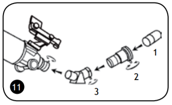
Barlow lens
A Barlow lens increases the magnifying power of an eyepiece, while reducing the field of view. It expands the cone of the focused light before it reaches the focal point, so that the telescope’s focal length appears longer to the eyepiece. In addition to increasing magnification, the benefits of using a Barlow lens include improved eye relief, and reduced spherical aberration of the eyepiece. For this reason, a Barlow plus a lens often outperform a single lens producing the same magnification. And the best advantage is that a Barlow lens can potentially double the number of eyepieces in your collection. (11)
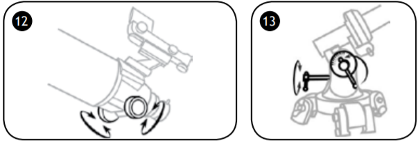
Focusing
Slowly rotate the focus knobs under the focuser one way or the other until the image in the eyepiece is sharp. The image usually has to be finely refocused over time, due to small variations caused by temperature changes, flexures, etc. Refocusing is almost always necessary when you change an eyepiece, add or remove a Barlow lens. (12)
Polar adjustment
In order for your telescope to track objects in the sky you have to align your mount. This means tilting the head over so that it points to the North (or South) celestial pole. For people in the Northern Hemisphere this is rather easy as the bright star Polaris is very near the North Celestial Pole. For casual observing, rough polar alignment is adequate. Make sure your equatorial mount is leveled and the finderscope is aligned with the telescope before beginning.
Look up your latitude on a map, road maps are good for this purpose. Now look at the side of your mount head, there you will see a scale running from 0 to 90°. Loosen the mount latch slightly rotating the lock handle counterclockwise. A thumbscrew located underneath the mount head pushes the latch plate, thus changing the angle. Turn the screw until the pointer on the latitude scale is set at the latitude of your observation site. (13)
Loosen the Dec. lock knob and rotate the telescope tube until the pointer on the setting circle reads 90°. Retighten the Dec. lock knob. Loosen the azimuth lock knob and move the mount so that the R.A. axis points roughly at Polaris. Use the two azimuth adjustment knobs above the “N” to make fine adjustments in azimuth if needed. For more accurate alignment, look through the finderscope and center the Polaris on the crosshairs using the azimuth and latitude adjustment knobs. After a while you will notice your target drifting slowly North or South depending on the direction of the pole relative to Polaris. To keep the target in the center of the view, turn only the R.A. slow-motion control.
After your telescope is polar aligned, no further adjustments in the azimuth and latitude of the mount should be made in the observing session, nor should you move the tripod. Only movements in R.A. and DEC axis should be made in order to keep an object in the field. In the Southern Hemisphere you must align the mount to the SCP by locating its position with star patterns, without the convenience of a nearby bright star. The closest star is the faint 5.5-mag. Sigma Octantis which is about one degree away. Two sets of pointers which help to locate the SCP are α and β Crucis (in the Southern Cross) and a pointer running at a right angle to a line connecting α and β Centauri. (14)
Tracking celestial objects
When observing through a telescope, astronomical objects appear to move slowly through the telescope’s field of view. When the mount is correctly polar aligned, you only need to turn the R.A. slow-motion control to follow or track objects as they move through the field. A R.A. motor drive can be added to automatically track celestial objects by counteracting the rotation of Earth. The rotation speed of the R.A. drive matches the rotation rate of Earth for stars to appear stationary in the telescope eyepiece. Different tracking speeds are also available in some models. A second drive can be added to give Dec. control which is very useful for astrophotography.
The quickest way to find objects is to learn the constellations and use the finderscope, but if the object is too faint you may want to use setting circles on an equatorial mount. Setting circles allow you to locate celestial objects whose celestial coordinates have been determined from star charts. Your telescope must be Polar aligned and the R.A. setting circle must be calibrated before using the setting circles. The Dec. setting circle was calibrated at the factory and no additional calibration is required for it. The telescope’s R.A. setting circle is scaled in hours, from 1 to 24, with small lines in between representing 10 minute increments. The upper set of numbers applies to observations in the Northern Hemisphere, while the numbers below them apply to observations in the Southern Hemisphere. (15)
Setting (calibrating) the R.A. setting circle
In order to set your Right Ascension circle you must first find a star in your field of view with known coordinates. A good one would be the 0.0 magnitude star Vega in the Constellation Lyra. From a star chart we know the R.A. coordinate of Vega is 18h 36m. Loosen the R.A. and DEC. lock knobs on the mount and adjust the telescope so that Vega is centered in the field of view of the eyepiece. Tighten the R.A. and DEC. lock knobs to lock the mount in place. Now rotate the R.A. setting circle until it reads 18h 36m. You are now ready to use the setting circles to find objects in the sky.
Pointing in any direction other than due North requires a combination of R.A. and Dec. positions. This can be visualized as a series of Dec. arcs, each resulting from the position of rotation around the R.A. axis. In practice however, the telescope is usually pointed, with the aid of a finderscope, by loosening both the R.A. and Dec. locks and swiveling the mount around both axes until the object is centered in the eyepiece. The swiveling is best done by placing one hand on the telescope tube and the other on the counterweight rod, so that the movement around both axes is smooth, and no extra lateral force is applied to the axis-bearings. When the object is centered, make sure the R.A. and Dec. locks are both retightened to hold the object in the field of view and allow tracking by adjusting R.A. only. (16)
Telescopes with long focal lengths often have a “blind spot” when pointing near the zenith, because the eyepiece-end of the optical tube bumps into the mount’s legs. To avoid this, the tube can be very carefully slipped up inside the ring clamps. This can be done safely because the tube is pointing almost vertically, and therefore moving it does not cause a Dec. balance problem. It is very important to move the tube back to the Dec. balanced position before observing other sky areas.
Something which can also be a problem is that the optical tube often rotates so that the eyepiece, finderscope and the focusing knobs are in less convenient positions. The diagonal mirror can be rotated to adjust the eyepiece. However, to adjust the positions of the finderscope and focusing knobs, loosen the tube rings holding the telescope tube and gently rotate it. Do this when you are going to observe an area for while, as it is inconvenient to repeat every time you briefly go to a new area.
Finally, there are a few things to consider to ensure that you are comfortable during the viewing session. First is setting the height of the mount above the ground by adjusting the tripod legs. You must consider the height that you want your eyepiece to be, and if possible plan on sitting on a comfortable chair or stool. Very long optical tubes need to be mounted higher or you will end up crouching or lying on the ground when looking at objects near the zenith. However, a short optical tube can be mounted lower so that there is less movement due to vibration sources, such as wind. This is something that should be decided before going through the effort of polar aligning the mount.
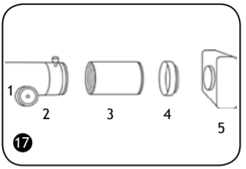
Camera adapter
To attach a camera to your telescope you may need an adapter to get the camera focused. Some reflectors require wider motion range than the one allowed by the focuser; some refractors are designed to be used with diagonal mirrors and thus need a longer focal length when used with camera. To achieve that, simply attach an extender to the focuser of your telescope and then attach
the camera with a T-adapter to the extender. (17)
Specifications
| Levenhuk Skyline PRO 80 MAK |
Levenhuk Skyline PRO 90 MAK |
Levenhuk Skyline PRO 105 MAK |
Levenhuk Skyline PRO 127 MAK |
|
| Telescope type | catadioptric | |||
| Optical design | Maksutov-Cassegrain | |||
| Objective lens diameter (aperture) |
80mm | 90mm | 102mm | 127mm |
| Focal length | 1000mm | 1250mm | 1300mm | 1500mm |
| Focal ratio | f/12.5 | f/13.9 | f/12.8 | f/11.8 |
| Highest practical power | 160x | 180x | 200x | 250x |
| Limiting stellar magnitude | 12.0 | 11.7 | 12.0 | 12.5 |
| Resolution threshold | 1.73arcsec. | 1.5arcsec. | 1.3arcsec | 1.1arcsec |
| Mount | EQ1 | EQ1 | EQ2 | EQ3 (3—2) |
| Eyepiece | SUPER 10mm 1.25”, SUPER 25mm 1.25” | |||
| Finderscope | Red Dot | |||
| Tripod (adjustable) | aluminum, 28.0—48.4in (710—1230mm) |
aluminum, 27.6—50.0in (700—1270mm) |
steel, 27.6—44.1in (700—1120mm) |
|
Levenhuk reserves the right to modify or discontinue any product without prior notice.
Care and maintenance
- Never, under any circumstances, look directly at the Sun through this device without a special filter, or look at another bright source of light or at a laser, as this may cause PERMANENT RETINAL DAMAGE and may lead to BLINDNESS.
- Take necessary precautions when using the device with children or people who have not read or who do not fully understand these instructions.
- Do not try to disassemble the device on your own for any reason, including to clean the mirror. For repairs and cleaning of any kind, please contact your local specialized service center.
- Protect the device from sudden impact and excessive mechanical force.
- Do not touch the optical surfaces with your fingers. To clean the telescope exterior, use only special cleaning wipes and special optics cleaning tools from Levenhuk.
- Store the device in a dry, cool place away from hazardous acids and other chemicals, away from heaters, open fire and other sources of high temperatures.
- Replace the dust cap over the front end of the telescope whenever it is not in use. This prevents dust from settling on the mirror or lens surfaces.
- Seek medical advice immediately if a small part or a battery is swallowed.
Batteries safety instructions
- Always purchase the correct size and grade of battery most suitable for the intended use.
- Always replace the whole set of batteries at one time; taking care not to mix old and new ones, or batteries of different types.
- Clean the battery contacts and also those of the device prior to battery installation.
- Make sure the batteries are installed correctly with regard to polarity (+ and −).
- Remove batteries from equipment that is not to be used for an extended period of time.
- Remove used batteries promptly.
- Never attempt to recharge primary batteries as this may cause leakage, fire, or explosion.
- Never short-circuit batteries as this may lead to high temperatures, leakage, or explosion.
- Never heat batteries in order to revive them.
- Remember to switch off devices after use.
- Keep batteries out of the reach of children, to avoid risk of ingestion, suffocation, or poisoning.
- Utilize used batteries as prescribed by your country laws.
Levenhuk International Lifetime Warranty
All Levenhuk telescopes, microscopes, binoculars and other optical products, except for accessories, carry a lifetime warranty against defects in materials and workmanship. Lifetime warranty is a guarantee on the lifetime of the product on the market. All Levenhuk accessories are warranted to be free of defects in materials and workmanship for six months from date of retail purchase. Levenhuk will repair or replace such product or part thereof which, upon inspection by Levenhuk, is found to be defective in materials or workmanship. As a condition to the obligation of Levenhuk to repair or replace such product, the product must be returned to Levenhuk together with proof of purchase satisfactory to Levenhuk. This warranty does not cover consumable parts, such as bulbs (electrical, LED, halogen, energy-saving and other types of lamps), batteries (rechargeable and non-rechargeable), electrical consumables etc.
For further details, please visit our web site: www.levenhuk.com/warranty If warranty problems arise, or if you need assistance in using your product, contact the local Levenhuk branch.