1. GENERAL INFORMATION
1.1 SYSTEM DESCRIPTION
The LE321-GR/RD LOW is a Class llla laser device that features a Visible Laser Pointer for daylight or low light operations, an IR Laser Pointer an IR Illuminator and LED Illuminator. The LE321-GR/RD LOW emits the highly collimated Visible Pointer and IR Pointer for all weather precise aiming. The Visible Pointer, IR Pointer and IR Illuminator are co-aligned.
1.2 COMPONENT DESCRIPTION
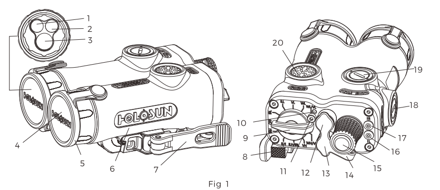
| 1 | Visible Laser | 6 | Battery Cabin | 11 | Security Screw | 16 | IR Illumination indiator |
| 2 | IR Laser Pointer | 7 | QR Lever | 12 | Remote Cable Switch | 17 | IR Laser Indicator |
| 3 | IR Illuminator | 8 | Handle Lock | 13 | DC Power Socket | 18 | Windage Adjustor |
| 4 | LED Illuminator | 9 | Mode Selector | 14 | Jack Cover | 19 | Elevation Adjustor |
| 5 | Protective Cover | 10 | Security Screw Store | 15 | Focusing Knob | 20 | Fire Button |
1.3 MODEL
There are two Model available : LE321-GR LOW & LE321-RD LOW. For LE321-GR LOW, the visible laser pointer is using 520 nm green laser for the LE321-RD LOW, the visible laser pointer is using 635 nm red laser. Other lights and functions are same with each other
1.4 PACKING
The package will contain with the following items:
- LE321 laser sight
- 1* CR123A battery
- Manual
- Remote cable Switch
- Date line with USB port
- Hex Wrench
2. FEATURES
- The Visible Pointer, IR Pointer and IR Illuminator are co-aligned so that the user could adjust three beams simultaneously via same adjuster.
- Highly collimated Visible Pointer and IR Pointer for quick, all-weather aiming.
- LE321-GR LOW employs 520nm semiconductor laser diode as its light source DPSS, which has more better features such as more energy-saving, brighter, more stable and wider thermal range than DPSS laser.
- Low-battery laser alert Indicators for IR pointing and IR Illumination status.
- Delayed auto power off.
- The IR illumination focus ranges is from 95 to 210 mrad.
- Remote cable switch could be connected with the sight.
- External power source could be used for power supplier.
- Ouick Release Mount.
- QD mount compatible with MIL-SID1913 rail.
- Titanium alloy housing.
3. SPECIFICATIONS
| Parameter | Wavelength (nm) |
|
Divergance (mrad) | FDA Class | ||||
| Green sight (LE321-GR LOW) | 520 |
|
0.6 | II/IIIa | ||||
| Red sight (LE321-RD LOW) | 635 |
|
0.6 | II/IIIa | ||||
| IR Laser sight | 830 |
|
0.5 | I / II | ||||
| IR Laser Illuminator | 830 |
|
Adjustable: 95-210 | I / II | ||||
| LED Illuminator | White |
|
8° | Eye-safe | ||||
| Adjustment Range | +50MOA | Water Proof | IP67 | |||||
| Battery | CR123Ax1 | Colour Housing | Desert Sand/ Matte Black | |||||
| Operating Temperature | -40℃ ~51 ℃ | Dimension (in) | 3.7 x 2.24 x 1.46 | |||||
| Storage Temperature | -40℃ ~70 ℃ | Weight (oz) | 9.52 |
4. OPERATING INSTRUCTIONS
4.1 SAFTY SUMMARY
WARNING – LASER RADIATION
- DO NOT stare into laser beams.
- DO NOT look into the laser beam through binoculars or telescopes.
- DO NOT point the laser beam at mirror-like surfaces.
- DO NOT shine the laser beam into other body’s eyes.

4.1.2 Safety Instruction for Illb class radiation
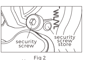
1. Operation under llla laser mode must follow specific procedure and in specific location.
2. Screw out the security screw by hex wrench and fix it into the security screw store.
3. After operation, re-fix the security screw into the original position. (Fig 2)
4.1.3 Caution
1. DO NOT store LE321-GR/RD LOW with battery installed.
2. Ensure the Mode Selector is OFF before checking the Lens of LE321-GR/RD LOW
3. Identifies risk of damage to the equipment.
4. All the directions are given from the shooter’s viewpoint.
5. DO NOT over-adjust the W&E adjuster by forcing them beyond their end of travel.
4.2 Battery

4.2.1 Battery installation (Fig 3)
- Rotating the battery cap in a CCW direction. Remove and properly discard the used battery.
- Inspect the battery compartment for dirt, moisture and corrosion, and then clean the battery compartment if needed.
- Inspect the O-ring seal on the battery cap to make sure that it is free of sand and dirt particles and that it has not been damaged.
- Install the battery in a direction marked on the nearby housing and then screw the battery cap in a CW direction.

4.2.2 External power Source(Fig 4)
This laser sight can be connected to external power source for its power supply. One end of the 4-pin power cable plug can be connected to the 4-pin socket, another end with USB port is connected to DC 5V power source.
4.2.3 Low Battery Indicator
When the LE321-OR/RD LOW is switch on either model V or mode IR, the flicker in a Visible Pointer or the IR Indicators represents the low battery situation.
4.3 Mounting Instruction
The repeatability accuracy is less than 2 MOA
4. 3.1 First Use(Fig 5):

1) Use screwdriver to loose the mount of LE321-GR/RD LOW in order to install the LE321-GR/RD LOW on the rail.
2) Open the handle lock and then load the LE321-GR/RD LOW on the pica tinny rail.
3) Latch the handle lock and use screwdriver to adjust the tightness.

4.3.2 Repeat Use(Fig 5):
1) Open the handle lock and then load the LE321-OR/RD LOW on the pica tinny rail.
2) Latch the handle lock.
4.4 Mode Selector (Fig 6):
The LE321-GR/RD LOW has 11 modes and is set at mode OFF. Please make sure the mode selector is at one of 11 modes and do not locate the mode selector at any position between two modes.
| Mode | Description |
| WL/VL | Low power LED illuminator and Low power green/red Pointer will be on |
| VL | Low power LED illuminator will be on when PRESS Fire Switch |
| WL | Low power green/red laser Pointer will be on when PRESS Fire Switch |
| ILL | Low power IR illuminator will be on when PRESS Fire Switch |
| IRL | Low power IR Pointer will be on when PRESS Fire Switch |
| OFF | No laser will be on when PRESS Fire Switch |
| NOTE: Take off the safety screw if use the modes below | |
| IRH | High power IR Pointer will be on when PRESS Fire Switch |
| ILH | High power IR illuminator will be on when PRESS Fire Switch |
| IRH/IH | High power IR illuminator and Low power IR Pointer will be on |
| VH | High power green/red laser Pointer will be on when PRESS Fire Switch |
| igh | High power LED illuminator and Low power green/red Pointer will be onV |
4.5 IR Laser indication and IR illumination focus adjustment.
1. IR laser indication: When IR laser is activated, “IR” indicato rlights up. IR illumination is activated, “IL” Indicator lights up
2. IR illumination focus adjustment: the Beam size can be adjusted by the adjusting knob which is at the rear end of the sight. The adjustment range
95 – 210 mrad (Fig 7)

4.6 Switch Instruction
After choose the output laser via Mode Selector Switch, uncover the lens cover. Both Switch Button and Remote Cable Switch can be used to activate the laser under the chosen mode.
4.6.1 Switch Button
Operation: (Fig 6)
- Momentary On Mode. Single press the core of Switch Button and hold it, the laser will be activated and last for one minute emitting until the Switch Button was released. If the press lasted over one minute, the power will be turned off.
- Continuous On Mode: Double press the Switch Button without holding, the laser will be activated and last for 5 minutes and then automatically turn off. The user also can press Switch Button once to turn off the unit manually.
4.6.2 Remote Cable Switch
Installation:
1) Uncover the socket protective cover (Fig 4).
2) Insert the plug of Remote Cable Switch into the Socket after matching the interfaces of plug and socket (Fig 8)

Operation:
1) Momentary On Mode: Single press button of Remote Cable Switch and hold it, the laser will be activated and last until the Switch Button was released.
4.7 Windage & Elevation Adjustment
2) Continuous On Mode: Double press the button without holding, the laser will be activated and last 5 minutes and then automatically turn off. The user also can press Switch Button once to turn off the unit manually.

ADJUSTOR:
| Adjuster | Position | Mark | Direction | Pointer Movement | ||||||
| Elevation Knob | Top |
|
|
|
||||||
| Windage Knob | Slide |
|
|
|
ADJUSTMENT: Use wrench or coin to rotate the adjuster as needed according to the instruction table above.
5. MAINTAIN
The LE321-GR/RD LOW is rugged, compact laser device that is designed to operate in severe environments. The exterior housing is made of aircraft grade aluminum and the other components are made of chemically resistant materials that will not be harmed by chemicals normally encountered during military operation. Operator maintenance is limited to the inspection and cleaning of the LE321-GR/RD LOW external surfaces, replacement of battery before each mission and removal of the battery after each mission.
6. WARRANTY
Holosun will furnish its standard form LIMITED WARRANTY in favor of its customers and the first end users of its products. The LE321-GR/RD LOW has a one year limited warranty on parts and workmanship from the date of purchase. The warranty is void if the serial number or the manufacturer’s labels affixed to the product has been removed or if the product has been misused, modified, neglected or has been disassembled prior to return to manufacturer. To the maximum extent permitted by law, Holosun’ election to repair or replace the device shall constitute the purchaser’s sole remedy in the event of a defect.
7. NON-WARRANTY INFORMATION
Non-warranty repairs are subject to an evaluation fee. LE321-GR/RD LOW units that are not covered by the warranty will be tested and evaluated for failure. Customer permission and payment terms will be obtained prior to perform any repairs.
8. RETURN INSTRUCTIONS
- For service, repair or replacement email:[email protected], call 909-594-2888
- Please provide the following information to assist technician to determine if the item is repairable:
1) Serial Number of the defective item.
2) Thorough description of the malfunction, defect or damage
3) An explanation as to how the malfunction, defect or damage occurred, if known. (NOTE: If the technician determines that the item is under warranty or should be returned for repair, a Return Material Authorization (RMA) number will be provided.) - LE321-GR/RD LOW should be followed to prevent any additional damage:
1) Be sure that the is free of all contaminants such as dirt or any other foreign material.
2) Remove the battery.
3) Place the Exit Port Covers over each of the lenses.
4) Place the LE321-GR/RD LOW in the Shipping Case or Carrying Case if available. If the Shipping Case is not available, individually package each LE321-GR/RD LOW unit being returned in a suitable container.
Place the LE321-GR/RD LOW and a copy of the test report or detailed description of the failure in a suitable packing/shipping container. Mark the package with the RMA number. Ship the fastest, traceable. Please refer to www.holosun.com for current and complete warranty information.