Digital NV Attachment Forward FN135/FN155 Instruction Manual
Pulsar Digital NV Attachment Forward F155

Specifications
| Model | FN135 | FN155 |
| SKU# | 78138 | 78108 |
| Optical characteristics | ||
| Generation | Digital | Digital |
| Magnification, x | 1 | 1 |
| Relative aperture, D/f` | 1:1.2 | 1:1 |
| Field of view (at 100m), angular degree / m | 6.7 / 11.7 | 4.8 / 8.4 |
| Max. Observation range of an animal 1.7 m high, m / yard, approx | 370 / 405 | 450 / 490 |
| Close-up range, m | 5 | 5 |
| Suggested optical magnification range of optical device, x | 2-6 | 4-8 |
| Electronic characteristics | ||
| Sensitivity of the device, mW, not more than, mW (wavelenght 780nm, resolution 25 lines/mm) | 3×10^(-5) | 3×10^(-5) |
| Sensitivity of the device, mW, not more than, mW (wavelenght 915nm, resolution 25 lines/mm) | 1.5×10^(-4) | 1.5×10^(-4) |
| Sensor type / resolution, pixel | CMOS / 702×526 | CMOS / 702×526 |
| Display type / resolution, pixel | AMOLED / 640×480 | AMOLED 640x / 480 |
| Detachable IR Illuminatior | ||
| Type / Wavelenght, nm | LED / 940 | LED / 940 |
| Operational characteristics | ||
| Operational voltage | 3.1-4.2 | 3.1-4.2 |
| Battery type / Capacity / Rated output voltage | Li-Ion Battery Pack IPS5 / 5000 mAh / DC 3.7V | |
| External power supply | 5V (USB) | 5V (USB) |
| Operating time on Battery Pack at t=22 °C (Wi-Fi on; IR off), h | 9 | 9 |
| Degree of protection (IEC60529), IP code | IPX7 | IPX7 |
| Operating temperature | -25 °C… +50 °C/-13 °F…122°F | |
| Dimensions, mm/inch | 135x92x77 / 5.3×3.6×3 | 272x92x77 / 10.7×3.6×3 |
| Weight (w/o Battery Pack and IR) , kg/oz | 0.41 / 14.5 | 0.48 / 16.9 |
| Characteristics of the monocular | ||
| Optical magnification, x | 5 | 5 |
| Eye relief, mm | 18 | 18 |
| Field of view, degree / m at 1000m | 7 / 122 | 7 / 122 |
| Dimensions (LxWxH), mm/inch | 147x68x68 / 5.8×2.7×2.7 | |
| Weight, kg/oz | 0.2 / 7 | 0.2 / 7 |
| Video recorder | ||
| Video resolution, pixel | 640×480 | 640×480 |
| Photo resolution, pixel | 640×480 / 1280×960 | 640×480 / 1280×960 |
| Video / photo format | .avi / .jpg | .avi / .jpg |
| Built-in memory | 16Gb | 16Gb |
| Built-in memory capacity | 300 min video / 20000+ photos | 300 min video / 20000+photos |
| Wi-Fi channel | ||
| Frequency | 2.4GHz | 2.4GHz |
| Standard | 802.11 b/g/n/ | 802.11 b/g/n |
| Line-of-sight reception range, m | 15 | 15 |
Package contents
- Digital module
- Cosmetic cover
- Monocular Pulsar 5×30
- Carrying case
- Wireless remote control
- IPS5 Battery Pack
- Battery charger with mains charger
- Quick-release IR Illuminator
- MicroUSB cable
- Lens/eyepiece protective covers
- User manual
- Lens cloth
- Warranty card
The design and firmware of this product are subject to change for development purposes.
The latest edition of this user manual is available at www.pulsar-nv.com
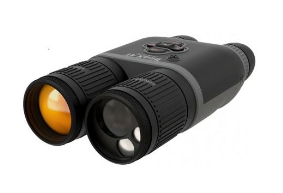
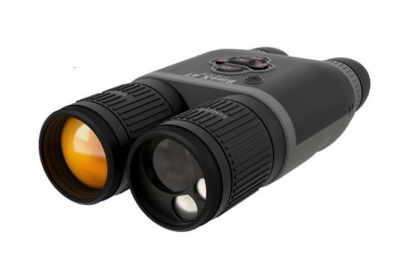
Description
Digital Night Vision Forward FN is a combination of a digital module and 5-power monocular for observation both in the twilight and daytime. To operate in total darkness the unit can be employed with an invisible IR Illuminator. The Forward FN can also be mounted on the majority of day binoculars or
monoculars by detaching the monocular Pulsar 5×30 and using adapter rings which enable its positioning on objective lenses with various diameters. In this manner you are able to convert your day optical device into a night vision device.
The Forward FN is designed for professional and amateur use, such as observation, security, night and day video recording.
Features
Key features:
- Enhanced nighttime sensitivity
- Easy to install and operate
- 5x monocular included
- Compact and lightweight
- Invisible 940 nm IR Illuminator
- Wi-Fi. Integration with iOS and Android devices
- Integrated video and sound recorder
- Fully waterproof (IPX7)
- Wide range of operating temperature (-25…+50°C)
- Updatable features
Other features:
- Stream Vision application. Remote review and operation using smartphone
- Recording and live YouTube streaming
- Quick four-point bayonet mount with automatic clamp
- Power bank charging via microUSB
- Full control of all device functions
Battery Pack
- Quick-change batteries IPS5/IPS10
- Wi-Fi up to 16 hours*
- Operation on AAor CR123 batteries **
- Charging IPS5/IPS10 batteries via USB (when the unit is on)
*on Battery pack IPS10 (sold separately).
** using a battery container (sold separately)
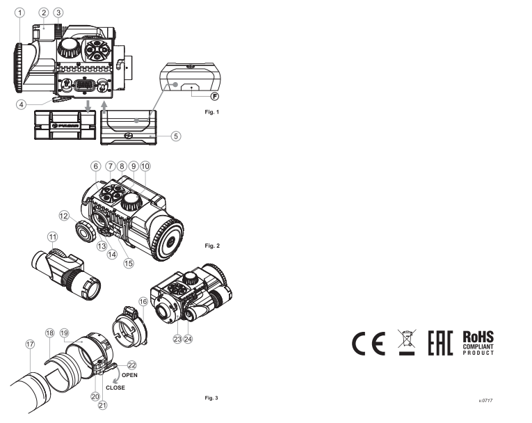
EXTERNAL VIEW AND CONTROLS
1-Lens cover
2-IR Illuminator hood
3-Locking ring
4-Lever
5-Battery Pack
6-Button RIGHT
7-Button M (MENU)
8-Button LEFT
9-Button ON
10-Lens focusing ring
11-IR Illuminator locking nut
12-IR Illuminator port plug
13-IR Illuminator mounting port
14-MicroUSB port
15-Weaver rail
16-Adapter’s cover
17-Optical device
18-Insert
19-Adapter
20-Locking screw
21-Screw
22-Adapter’s lever
23-Mounting block
24-Button IR
Please see the scheme on the flyleaf.
DESCRIPTION OF CONTROLS
|
Button |
Current operating mode | First short press | Other short presses | Long press |
|
ON (9) |
Unit is off | Power unit on | Display ON / OFF | Power unit off |
| Unit is on | Display off | Display ON / OFF | ||
|
LEFT(8) |
Unit is on | SumLight ON | SumLight OFF | Wi-Fi ON Wi-Fi OFF |
| Menu navigation | Downwards/Leftwards | |||
|
MENU(7) |
Unit is on | Enter quick menu | Enter main menu | |
| Menu navigation | Confirm selection | Exit submenu without confirming selection / Exit menu (switch to viewing mode) | ||
|
RIGHT(6) |
Unit is on («Video» mode) | Start video recording | Pause / resume video recording | Stop video recording/ Switch to photo mode |
| Unit is on («Photo» mode) | Take a photograph | Switch to video mode | ||
| Menu navigation | Upwards/rightwards | |||
GUIDELINES FOR OPERATION
The unit has been designed for long-term use. To ensure long performance, please adhere to the following:
- Before use make sure that you have mounted the unit according to the instructions.
- Turn the unit off after use.
- Attempts to disassemble or repair the unit will void the warranty!
- The unit can be used in various operating temperatures. However, if it has been brought indoors from cold temperatures, do not turn it on for 3 to 4 hours. This will prevent external optical surfaces from fogging.
- To ensure reliable performance, it is recommended to carry out regular technical inspections of the unit.
- The battery shall not be exposed to excessive heat such as sunshine, fire or the like.
- Do not leave the battery in the unit in case of a long-term storage.
USING THE BATTERY PACK
The unit is supplied with a rechargeable Li-Ion Battery Pack IPS5 which allows operation for up to 9 hours. Please remember to charge the Battery Pack before first use.
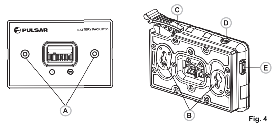
Charging:
- Remove the protective cover from the Battery Pack.
- Install the Battery Pack into the charger by inserting the pins (A) of the battery into the grooves (B) of the charger- the Pulsar logo on the battery Pack should be located closer to the lever; click the lever (C) (Fig.4).
- upon installation, a green LED indicator (D) on the charger will start to glow and begin flashing:
-once if the battery charge ranges from 0%-50%;
-twice if the battery charge ranges from 51% to 75%
-three times if the battery charge ranges from 75% to 100%;
- If the indicator lights green continuously, the battery is fully charged.
- You can remove the battery from the charger by lifting the lever (C).
- If the indicator of the charger lights red continuously upon battery installation, probably the battery`s charge level is lower than acceptable (the battery has been long in deep discharge). Keep the battery in the charger for a long time (up to several hours), remove and re-insert it. If the indicator starts blinking green, the battery is good; if it keeps lightning red it`s defective. Do not use the battery!
- Connect the Micro-USB plug of the USB cable to the port (E) of the charger.
- Connect the Micro-USB plug to the charger.
- Insert the plug pf the charger to he 220V socket.
Installing the battery pack into device:
- Remove the decorative cover from the digital module.
- Lift the lever (4)
- Install the battery (5) into the dedicated slot on the device housing so that element F (see Pic.1 on the flyleaf) appears from below.
- Fix the battery by clicking the lever.
Safety measures:
- Only use the charger supplied with the Battery Pack. The use of any other charger may irreparably damage the Battery Pack or the charger and may cause fire.
- When keeping the battery for a long period, it should not be fully charged or fully discharged.
- Do not charge the battery immediately after bringing the battery from cold environment to a warm one. Wait for 30-40 minutes for the battery to get warm.
- Do not leave a battery unattended while charging.
- Never use a modified or damaged charger.
- Charge the Battery Pack at a temperature ranging from 0 °C to +45 °C.
- Otherwise batter’s life will decrease significantly.
- Do not leave the Battery Pack with a charger connected to the mains longer than 24 hours after full charge.
- Do not expose the battery pack to high temperature or to a naked flame.
- Do not submerge the battery in water.
- Do not connect external device with a current consumption that exceeds permitted levels.
- The Battery Pack is short circuit protected. However, any situation that may cause short-circuiting should be avoided.
- Do not dismantle or deform the Battery Pack.
- Do not drop or hit the battery.
- When using the battery at negative temperatures, battery’s capacity decreases, this is normal and is not a defect.
- Do not use the battery at the temperatures above those shown in the table – this may decrease battery’s life.
- Keep the battery out of the reach of children.
EXTERNAL POWER SUPPLY
The unit can be powered with an extrenal power supply such as Power Bank (5V).
- Connect the external power supply to the USB port (14) of the attachment.
- The unit switches to operation from external power supply and the IPS5 Battery Pack will begin slowly charging.
- The display will show the battery icon
 with the charge level as a percentage.
 - If the unit is connected to a PC or mains charger/power bank which does not comply with the Battery Charger (BC 1.0) standard, the IPS5 Battery Pack will not be charging; only external power supply icon will be shown
- If the unit operates on external power supply but the IPS5 battery is not connected, the icon is shown.
- When the external power supply is disconnected, the unit switches to the internal battery pack without powering off.
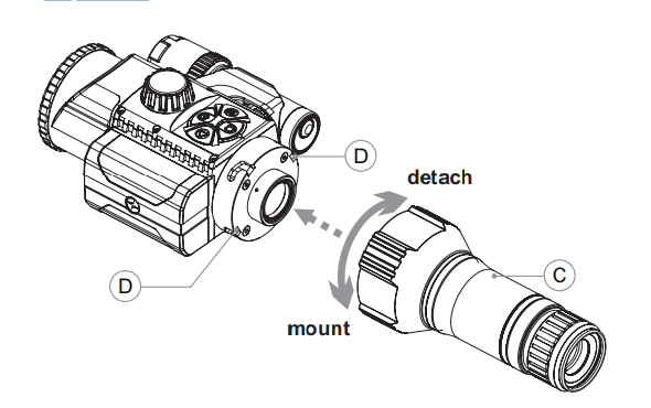
MOUNTING THE MONOCULAR ON DIGITAL MODULE
- The monocular Pulsar 5×30 (C) (included) converts the digital module into a 5x digital night vision device.
- Insert the monocular firmly so that the pins in the monocular’s body enter the notches (D) of the digital module.
- Turn the monocular fully counterclockwise to fix it on the digital module.
- In order to remove the monocular, turn the monocular clockwise and pull carefully.
OPERATION
Mounting the attachment on daylight device
- Choose an adapter with an insert of the required diameter depending on the outer diameter of the bell of the daylight device.
- The figures 42 mm, 50 mm, 56 mm in adapter’s model name correspond to the optical diameter of the device’s bell.
- Measure the outer diameter of the housing of your device’s bell and select an insert in accordance with reference data in the tables below.
Example. If the lens diameter of your day device is 42 mm, and the measured outer diameter of the housing of the device’s bell is 47.2 mm, you need to use an insert with marking “Ø 47”. Compatibility chart of inserts for the day devices.
Compatibility chart of inserts for the day devices
| Cover Ring Adapter model | Insert`s inner diameter, mm | Outer diameter of day device`s lens, mm |
| Cover Ring Adapter FN 42 mm | 47
48 49 50 |
46.7-47.6
47.7-48.6 48.7-496 49.7-50.6 |
| Cover ring adapter FN 50 mm | 55
56 57 58 |
54.7-55.6
55.7-56.6 56.7-57.6 57.7-58.6 |
| Cover ring adapter FN 56 mm | 59
60 61 62 63 64 65 |
58.7-59.6
59.7-60.6 60.7-61.6 61.7-62.6 62-7-63.6 63.7-64.6 64.7-65-6 |
- Remove the cover (16) from the Cover Ring Adapter (19) by turning it counterclockwise.
- Put the insert (18) into the adapter, unsnap the clamp (22) of the adapter (19) and firmly mount the adapter on the device’s bell (17) to ensure that the surface in the bottom part of the adapter is located above the barrel.
- Before installing it is advised to degrease the device’s bell.
- Install firmly the insert (18) into the adapter (19) (Pic.3).
- Install firmly the adapter with insert onto the lens of your day device
(Pic.3) - Snap the lever (22) from the original OPEN position to the CLOSE position (Pic.3).
- Check that the adapter firmly fits the objective lens.
- If you see there is a clearance, please:
– Loosen the locking screw (20) with the hex-nut wrench (S=2mm).
-Tighten the screw (21) with hex-nut wrench (S=4mm).
- Recommended clamping force is 1 N·m (can be checked with the help of a torque screwdriver).
-Tighten the locking screw(20).
- Insert firmly the device into the adapter so that the teeth in the adapter’s body enter the notches of the device. Turn the device clockwise against the stop. Triangle-shaped marking on the device and the square-shaped marking on the adapter should match.
- To align the attachment, move the lever (22) to the OPEN position and align horizontally.
Powering on and image setup
- Remove the lens cover (1) by turning it counterclockwise.
- Turn the unit on with a short press of the ON (9) button.
Image appears on the display in several seconds. - To obtain a crisp image of the icons on the display, rotate the dioptre adjustment ring of your optical device. After this there is no need to rotate the dioptre adjustment ring for distance or any other conditions.
- To focus on the object being observed rotate the lens focusing ring (10).
- To set up display brightness and contrast, please refer to the QUICK MENU FUNCTIONS section.
- After use, hold down the ON button to turn the unit off.
QUICK MENU FUNCTIONS
The quick menu allows setup of display brightness and contrast.
- Enter the menu with a short press of the M(7) button.
- To toggle between the functions below, press successively the M button.
- Brightness – press the RIGHT (6) and LEFT (8) buttons to change display brightness from 0 to 20.
- Contrast– press the RIGHT (6) and LEFT (8) buttons to change display contrast from 0 to 20.
MAIN MENU FUNCTIONS
- Enter the menu with a long press of the М (7) button. To toggle between the main menu options, press the RIGHT (6) and LEFT (8) buttons.
- Enter a submenu of the main menu with a short press of the М button.
- Exit the submenu with a long press of the М button.
- Automatic exit takes place in 10 sec of inactivity.
- Upon exit from the menu the cursor location is memorized only for the duration of the working session (i.e. until the unit is turned off).
- Upon restarting the unit and entering the menu the cursor will be located on the first menu option.
MENU CONTENTS:
- Microphone
Digital NV Attachment Forward FN135/FN155 Instruction Manual - Wi-Fi settings
- General settings:
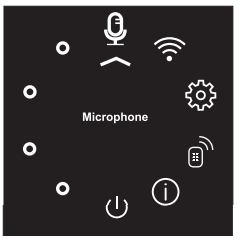
-Language
-Date
-Time
– Photo resolution
-Factory reset
-Formatting
- Remote control activation
- Device information
- Automatic shutoff
Microphone
The build-in microphone is designed to capture sound when recording video.
- Enter the menu with a long press of the M (7) button.
- Press the RIGHT (6) and LEFT (8) buttons to select submenu “Microphone”.
- Enter the submenu with a short press of the M button.
- Press RIGHT or LEFT (sliders `s position off).
- To deactivate the microphone press briefly RIGHT or LEFT (slider`s position On).
 select submenu “Microphone”.
Wi-Fi Settings
This menu option allows you to set up your unit for operation in a Wi-Fi network
Password setup
This submenu allows you to set a password to access your unit from an external device. The password is used to connect an external device (i.e. smartphone) to your Forward FN. Enter the menu with a long press of the М (7) button.
Press the RIGHT (6) and LEFT (8) buttons to select submenu “Wi-Fi
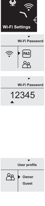
Settings”.
- Enter the submenu with a short press of the М
button. - Press RIGHT or LEFT to select item “PAS”.
- Enter the item with a short press of the М button.
- The default password “12345” appears on the
display. - Set the desired password with RIGHT or LEFT (button RIGHT to increase value; button LEFT to reduce). Switch between digits with a short press of the M button.
- Save the password and exit the submenu with a long press of the M button.
Access level setup
This submenu allows you to set required access level of the Stream Vision application to your unit.
- Select item “Access level setup” in submenu “Wi-Fi Settings” with the RIGHT (6) and LEFT (8) buttons.
- Enter the submenu with a short press of the М button.
- Select access level “Owner” or “Guest” with the RIGHT (6) and LEFT (8) buttons.
-
-
- Access level Owner. The Stream Vision user has the complete access to all functions of the unit.
- Access level Guest. Stream Vision user has the access only to the real time video stream from the unit.
- Save your selection and exit the submenu with a long press of the M button.
-
-
General settings

The following settings are available:
Language
- Enter the menu with a long press of the M (7) button.
- Press the RIGHT (6) and LEFT (8) buttons to select submenu “General Settings”.
-
-
- Enter the submenu with a short press of the M button.
- Press RIGHT or LEFT to select item “Language”.
- Enter the item with a short press of the M button.
- Select one of the available interface languages with the RIGHT or LEFT buttons: English, French, German, Spanish.
- Save your selection and exit the submenu with a long press of the M button.
-
-
Date setup

- Enter the menu with a long press of the M button.
- Press the RIGHT (6) and LEFT (8) buttons to select submenu “General Settings”.
- Enter the submenu with a short press of the M button.
- Press RIGHT or LEFT to select item “date”.
- Enter the item with a short press of the M button.
- Date format is displayed as: DD/MM/YYYY (21/04/2017).
-
-
- Select a correct values for the year, month and day with a short press of the RIGHT and LEFT buttosn (button RIGHT to increase value; button LEFT to reduce). Switch between digits with a short press of the M button.
- Save selected date and exit the submenu with a long press of the M button.
-
-
Time setup

- Enter the menu with a long press of the M button.
- Press the RIGHT (6) and LEFT (8) buttons to select submenu “General Settings”.
- Enter the submenu with a short press of the M button.
-
-
- Press RIGHT or LEFT to select submenu “Factory reset”.
- Enter the submenu with a short press of the M button.
- With a short press of the RIGHT or LEFT buttons select “Yes” to restore default settings or “No” to abort.
- Confirm selection with a short press of the M button.
- The following settings will be restored to their original values before changes made by the user:
-
-
| Display brightness | 10 |
| Display contrast | 6 |
| Language | English |
| Microphone | OFF |
| Video resolution | 640×480 |
| Photo resolution | 640×480 |
| Wi-Fi | OFF (default password) |
| Automatic shutoff | OFF |
Photo resolution
- Enter the menu with a long press of the M button.
- Press the RIGHT (6) and LEFT (8) buttons to select submenu “General Settings”.
- Enter the submenu with a short press of the M button.
- Press RIGHT or LEFT to select submenu “Photo resolution”.
- Enter the submenu with a short press of the M button.
- Select photo resolution with RIGHT (6) and LEFT (8):
- 640×480 pixel
- 1280×960 pixel
- Confirm selection with a short press of the M button.
Formatting
Formatting of the integrated memory card will irrevocably delete all saved files.
![]() Make sure that you do not need the files to delete or back up the files using an alternative carrier.
Make sure that you do not need the files to delete or back up the files using an alternative carrier.
- Enter the menu with a long press of the M button.
- Press the RIGHT (6) and LEFT (8) buttons to select submenu “General Settings”.
- Enter the submenu with a short press of the M button.
- Press RIGHT or LEFT to select submenu “Format”
- Enter the submenu with a short press of the M button.
- With a short press of the RIGHT and LEFT buttons select “Yes” to format or “No” to abort.
- Confirm selection with a short press of the M button.
Remote control activation
The remote control duplicates unit`s major functions.
Before operating the remote control, remember to activate it as follows:
- Enter the menu with a long press of the М (7)
button. - Press the RIGHT (6) and LEFT (8) buttons to
select submenu “Remote control”. - Enter the submenu with a short press of the М
button. Countdown starts (30 sec), within which
hold down any RC button for two seconds. - If activation is successful, the message
«Connection complete» appears. If error
occurs the message «Connection failed»
appears. Repeat the procedure. - The RC is activated and ready for use.
Device information
- Enter the menu with a long press of the М (7)
button. - Press the RIGHT (6) and LEFT (8) buttons to
select submenu “Device information”. - Enter the submenu with a short press of the М
button. - This option allows the user to view the following information about the device:
- full name
- SKU number
- serial number
- software number
- hardware number
- service number
Automatic shutoff
This option allows you to activate automatic shutoff which determines whether your unit is in a working position. Automatic shutoff is actuated after you move the unit relative to the optical axis: > 70° Upwards or downwards; >30°Leftwards or
rightwards; and if no controls are used.
- Enter the menu with a long press of the М (7) button.
- Press the RIGHT (6) and LEFT (8) buttons to select submenu “Auto shutoff”.
- Enter the submenu with a short press of the М button
- With the RIGHT and LEFT buttons select the time period (1 min, 3 min, 5 min) upon expiry of which the unit will automatically shut down. Select “Off” if you wish to deactive Auto shutoff.
- – Save your selection with a long press of the M button.
Note: respective icons on the status bar show
the status of the function:
– off: ![]()
– auto shutoff time (i.e. 1 min): 1 min
STATUS BAR
The status bar is located in the lower part of the display and shows information on the actual operating status of the unit, including:
- Function SumLight
- Automatic shutoff
- IR Illuminatro level (i.e. degree 3)
- Microphone activation
- Wi-Fi connection
- Clock
- Battery charge level (if the attachment is powered by the Battery Pack) or
- External battery power indicator (if the attachment is powered by an external power supply) or
- battery charge with current level in per cent (if battery is installed or it is being charged by external power supply)

IR ILLUMINATOR
The unit is equipped with a detachable IR Illuminator with a wavelength of 940 nm which allows the user to increase observation range in lowlight or in complete darkness.
- Make sure that the IR Illuminator is mounted and connected to the attachment – the display will show iconof the connected or disconnected IR Illuminator.
- To activate the IR Illuminator: turn the unit with the ON button, press briefly the IR button (24) on the edge of the IR Illuminator. Default IR.
- Power level is minimal (IR1). IR Illuminator icon with respective power level is shown in the bar status.
- To switch between power levels ( or ) press briefly the IR
button. - To focus the IR spot, rotate the IR Illuminator hood (2).
- To deactivate the IR Illuminator, hold down the IR button.
- To remove the IR Illuminator, rotate the IR locking nut (11)
counterclockwise. Screw the port plug (12). - Instead of the supplied IR Illuminator you can mount:
– laser IR Illuminator Pulsar Ultra AL-915 (#79138) operating at
915nm
– LED IR Illuminator Pulsar Ultra-940 (#79139) operating at 940nm
Notes:
- Upon turning the IR off, power level is not saved in the unit’s memory. Upon turning on, the IR Illuminator switches to the minimum power level – IR1.
- In order to align the IR spot vertically or horizontally, turn the locking ring (3) 5-10 degrees counterclockwise. Move the IR Illuminator hood (2) to match the spot with the image seen through the unit. Tighten the locking ring.
WI-FI FUNCTION
Your unit features wireless connection option (Wi-Fi) which links it with external appliances (tablet, smartphone).
Turn on the wireless module the with a long press of the LEFT (8) button. Wi-Fi operation is shown in the status bar as follows:
| Connection status | Status bar indication |
| Wi-Fi off | No icon |
| Wi-Fi activated by the user, Wi-Fi is being activated |
|
| Wi-Fi is on, no connection with attachment |
|
| Wi-Fi is on, Wi-Fi is on, attachment connected |
- Your unit is detected by an external device as «Forward FN_XXXX», where XXXX – is the last four digits of attachment’s serial number»
- After a password is generated on an external appliance (please refer to the menu option “Wi-Fi setup” of the section “Main menu functions” of this user manual) and connection is established, the iconin the status bar changes to; transmission of the video signal to the
display of external device starts automatically.
“SUMLIGHT ” FUNCTION
- “SumLight” function substantially incerases sensetivity of the CMOS array thus enabling observation in low light without using the IR Illuminator.
- To activate the function “SumLight”, press briefly the LEFT (8). button.
- To deactivate the function, press briefly the LEFT button again.
- Icon “SumLight” (on S or)
Attention! Please note that higher sensisivity causes an increased noise level in the picture, lower frame rate; image slows down, if the attachment is rapidly moved from one side to the other , the picture may be blurred for a moment.
Neither of these effects is a flaw of the unit. After the SumLight Signal Processing Program is activated, light dost (pixels) may appear in the filed of view which is explained by operation peculiarities of this function.
This is not a defec either.
VIDEO RECORDING AND PHOTOGRAPHY
The unit features video recording and photography of the image being saved to the internal memory card.
Before using this feature, please read the menu options “Date setup”, “Time setup” of the section “Main menu functions”.
The built-in recorder operates in two modes:
– Photo (photography; in the top right corner of the display you cansee a photography icon),
If estimated number of photos that can be saved to the Flash card is more than 100, message «>100» is shown.
– Video (video recording; in the top right corner of the display you can see a video icon, current video resolution, total video time left in the format HH:MM:SS (hours : minutes : seconds)
When switched on, the unit is in the Video mode. Toggle between Video and Photo modes witah a long press of the RIGHT (6). Switching is cyclical (Video->Photo->Video…).
Photo mode. Photography
Switch to the Photo mode with a long press of the RIGHT (6) button. Take a picture with a short press of the RIGHT button. The image freezes for 0.5 seconds and a photo is saved in the internal memory.
Video mode. Video recording
- Switch to the Video mode with a long press of the RIGHT (6) button.
- Start video recording with a short press of the RIGHT button.
- Upon start of video recording icon disappears, icon rec and recording timer in format MM:SS (minutes : seconds) appear instead.
- Pause and resume recording video with a short press of the RIGHT button.
- Stop recording video with a long press of the RIGHT button.
Video files are saved to the memory card:
- you can enter and navigate the menu during video recording:
- recorded videos and photos are saved to the build-in memory card in the format img_xxx.jpg (photos); videos_xxx.avi (videos). xxx – three-digit counter for videos and photos.
- counter for multimedia files cannot be reset
- if a file is deleted from the middle of the list, its number is not taken by another file.
- when the counter is full, a new folder is created- img-xxxx. Where xxxx is folder counter.
- the maximum duration of a recorded file is seven minutes. After this time expires a video is recorded into a new file. The number of recorded footage to other storage media to free up space on the internal memory card;
- graphic data (status bar, icons and other) are not shown in recorded video/photo files.
To playback video files recorded by the unit on iOS-based computers, we recommend that you use VLC video player or Elmedia player.
Download links and QR codes are shown below:

VLC VIDEO PLAYER
http://www.videolan.org/vlc/download-macosx.html

ELMEDIA VIDEO PLAYER
http://www.videolan.org/ vlc/download-macosx.html
https://itunes.apple.com/us/app/elmedia-multiformat-video/id937759555?mt=12
FUNCTION DISPLAY OFF
The DISPLAY OFF function activates stand-by mode which allows the unit to be quickly powered on.
Operating scenarios for the «Display off» function:
Scenario 1. The unit is turned off. Turn the unit on and activate
«Display off»
- Turn on the unit on with a short press of the ON (9) button.
- Activate «Display off» with a long press of the ON button.
Message “Display off” with countdown appears. - Release the ON button.
Scenario 2. «Display off» is on, the unit needs to be turned off.
- Hold down the ON button. Message “Display off” with countdown appears (1,2,3).
- Hold down the ON button until the unit turns off (the unit turns off after 1 is reached).
STREAM VISION
Forward FN supports Stream Vision technology which allows you to stream an image from the display of your unit to a smartphone or PC tablet via Wi-Fi in real time mode. You can find further guidelines on Stream Vision on our web site www.pulsar-nv.com
Note: the Stream Vision application allows you to update the firmware features of your unit.
Scan the QR codes to download Stream Vision free of charge:
Google Play (Android OS): iTunes (iOS):


USB CONNECTION
- Connect one end of the USB cable to the Micro-USB (14) port of your unit, and the other end to the USB port of your PC/laptop.
- Turn the unit on with a short press of the ON (9) button (unit that has been turned off cannot be detected by your computer).
- Your unit will be detected by the computer automatically; no drivers need to be installed.
Two connection modes will appear on the display:
- Memory card (external memory) and Power.
- Select connection mode with the RIGHT (6) and LEFT (8) buttons.
- Confirm selection with a short press of the M (7) button.
Connection modes:
Memory card (external memory). In this mode the unit is detected by the computer as a flash card. This mode is designed for work with the files saved in attachment’s memory. Unit’s functions are not available in this mode; the unit turns off automatically.
If video recording was in progress when connection was made,
recording stops and video is saved.
Power
In this mode your PC/laptop is used as an external power supply. The status bar shows icon . The unit keep on operating and all functions are accessible.
Note: The Battery Pack installed in the attachment is not being charged!
USB disconnection.
When USB is disconnected from the unit where connection is in the USB Mass storage mode, the unit remains on the OFF state. Turn the unit ON for further operation.
When USB is disconnected from the unit when in the Power mode, the unit turns off.
WIRELESS REMOTE CONTROL
The wireless remote control (RC) duplicazes the POWER OFF function video start/stop and menu navigation.
The RC controls are:
- Button on (25): partially duplicates the functions of the ON (9) button.
- Button IR (26): IR illumination operation.
- Button RIGHT (27) : duplicates the functions of the RIGHT (6) button.
- Controller (28): duplicates the functions of the M
Digital NV Attachment Forward FN135/FN155 Instruction Manual (7) button when pressed;
- duplicates the functions of the RIGHT (6) button and LEFT(8) upon rotation (in hot menu/main menu).

| Controller (28) | Button ON (25) | Button IR (26) | Button RIGHT (27) | |
| Short press | Enter hot menu | Dispaly off | IR1-IR2-IR3-IR4 | REC |
| Long press | Enter main menu | Turn unit off | Turn IR off | SumLight |
| Clockwise rotation | Increase value | – | – | – |
| Counter-clockwise rotation | Decrease value, downward movement | – | – | – |
USER THE WEAVER RAIL
The unit is equipped with a Weaver rail (15) which allows the user to mount extra accessories (please remove the IR Illuminator before using the rail), such as:
- LED IR Illuminators Pulsar-805/Pulsar-904/Pulsar-X850 (#79071/79076/97074)
- Laser IR Illuminators Pulsar AL915 (#79132)
TEHNICAL INSPECTION
Please check:
- External view (there should be no cracks on the housing).
- Correct mounting of the attachment on your optical sight (clearances are not allowed).
- the state of the Battery Pack (should be charged) and electric terminals (there should be no oxidation).
- Correct functioning of the controls.
MAINTENANCE
Maintenance should be carried out at least twice a year, and should consist of the following measures:
- Wipe external plastic and metal surfaces clean of dust and dirt with a soft cloth moistened with a synthetic cleaning agent.
- Clean the electric terminals of the Battery Pack and unit’s battery slot using a grease-free organic solvent.
- Check the objective and eyepiece lenses. If required, remove dust and sand (preferably by a noncontact method). Clean the external surfaces of the lenses with products expressly designed for this purpose.
STORAGE
Always store the unit in its carrying case in a dry, well-ventilated
space. For prolonged storage, remove the battery.
TROUBLESHOOTING
The table presented below lists some potential problems that may occur when using the unit. If a problem encountered is not listed, or if the recommended action does not resolve the problem, the unit should be returned for repair.
| Problem | Check | Corrective action |
| The unit will not turn on. | Battery Pack is discharged. | Charge the battery. |
| The unit does not operate on external power supply | USB cable is damaged | Replace USB cable. |
| External power supply is discharged | Charge the external power supply (if necessary). | |
| Image is too dark. | Brightness or contrast level is too low. | Adjust brightness/contrast level. |
| The unit will not focus. | The unit is wrongly adjusted. | Adjust the unit according to the instructions given in the Section “OPERATION” and check the surfaces of the eyepiece and objective lenses and clean them if necessary from dust, condensation, frost, etc; to prevent fogging in cold weather, apply a special antifog solution. |
| Wireless remote control will not operate. | Remote control is not activated. | Activate the remote control according to instructions. |
| Low battery | Install a new CR2032 battery | |
| Smartphone or tablet PC cannot be connected to the unit. | Password in the unit was changed.
There are too many Wi-Fi networks in the area where the unit is located which may cause signal interference |
Delete network and connect again inserting the password saved in the unit.
To ensure stable Wi-Fi performance, move the unit to an area with few or no Wi-Fi networks |
| Poor image quality / Detection range reduced | Problems described may arise in adverse weather conditions (snow, rain, fog etc.). | |
| Barely visible texture which does not hinder detection range or efficiency of observation can be noticed on the display after the extra laser IR Illuminator (AL915) is activated. | This is normal for eye safe laser IR illuminators. | This is not a defect. |
| The clamp of the adapter cannot be opened | Wrong insert is chosen. | Choose the appropriate insert. Check the gap between the lips of the adapters. |