Products mentioned:
PRESENTATION
Aimpoint® red dot sights are designed for the ”two eyes open” method which greatly enhances situational awareness and target acquisition. The red dot follows the movement of the user’s eye while remaining fixed on target, eliminating any need for centering.
Technical specification
| Optical system | |
| Magnification | 1X |
| Eye relief | Unlimited |
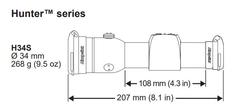
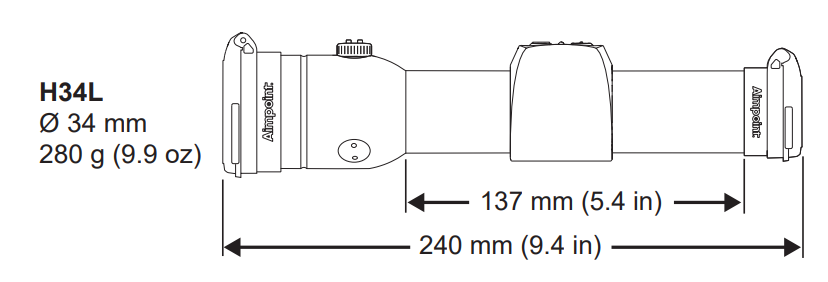
| Clear aperture | 29 mm / 1.1 in (H34S, H34L) |
| Dot size | 2 MOA |
| NVD2 compatible | No |
| Optical coating | Anti-reflection (AR) coating |
| Adjustments | 1 click = 20 mm at 100 m / 0.7 in at 100 yds |
| Adjustment range | ±1 m at 100 m / ±1 yds at 100 yds |
| Dot intensity settings | Digital touch pad, 12 settings |
| Dot color | Red (650 nm ± 10 nm) |
| Signatur | No forward optical signature from the dot beyond 10 meters |
| Power source | |
| Battery type | One CR2032 Lithium battery (3 V) |
| Battery life | More than 5 years of use at pos. 7 |
| Materials | |
| Sight | High strength aluminum, black to dark gray, non-glare finish |
| Touch pad | Silicon rubber |
| Lens covers | Thermoplastic elastomer, black, non-glare finish |
| Environmental specification | |
| Temperature range (operation) | -30 °C to +60 °C / -22 °F to +140 °F |
| Water resistance | Fully waterproof |
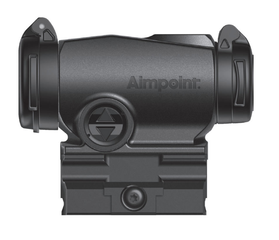
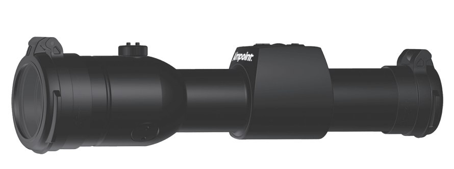
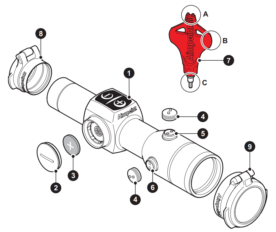
Overview
See Fig. 2
- Digital intensity touch pad
- Battery cap
- Battery (CR2032)
- Adjustment cap (2 pcs)
- Elevation adjustment screw
- Windage adjustment screw
- Tool (3 functions)
- Lens cover, rear
- Lens cover, front
OPERATION
WARNING: Ensure the weapon is not loaded and the safety selector is in the ”safe” position before attempting to install, remove or perform maintenance.
- Start the sight by pushing + or − on the intensity adjustment touch pad (1) located on top of the sight.
- The intensity of the dot starts at setting 7 of 12.
- Turn the sight off by holding the − button down for 1.5 seconds.
Installing Battery
Remove battery cap (2) by turning it counter clockwise using the plastic adjustment tool (7B) included with your sight.
Insert battery (3) with positive end (+) toward battery cap (2) as can be seen in Fig 2.
CAUTION: Check that the O-ring is in good condition and in position to ensure that there will be no water leakage into the battery compartment.
Install battery cap (2) by carefully aligning the threads on the battery cap (2) with the threads in the sight body, then turn the battery cap (2) clockwise until snug. Hand tighten only using the adjustment tool (7B).
Verify that red dot is present by pressing + or − intensity buttons (1) on the sight.
NOTE: Remove battery before putting the sight in storage for extended periods.
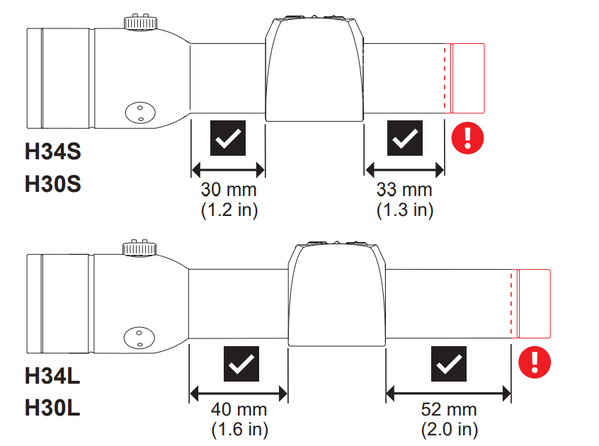
Installing Rings and Sight on the firearm
WARNING: Mounting any optical device too close to the user’s eye can cause the device to impact the shooter’s face or eyes during recoil, possibly causing severe injury. If you are unfamiliar with mounting optics on firearms, or in choosing the appropriate parts to mount your sight, please consult your dealer, gunsmith or other qualified source.
Aimpoint® Hunter Series sights are designed for installation on most types of hunting rifles and shotguns. The H30L and H34L are designed to provide sufficient space between the front and rear mounts for use on long and magnum action rifles. The H30S and H34S are designed for standard length action rifles and many types of shotguns.
NOTE: The use of Hunter Series sights is not recommended on super magnum revolvers (S&W 500, S&W 460SVR etc). Due to the extreme recoil forces andframe movement produced by these firearms, optics must be mounted using two heavy duty steel mounting rings and a solid one piece mounting base designed
specifically for use with these revolvers. Please consult your Dealer or qualified gunsmith for more information.
For mounting, use two good quality scope rings, and mount bases designed specifically for use on your firearm. Care must be taken to ensure that mounting the sight does not interfere with the safe operation of your firearm or obstruct the ejection of empty cases or shells.
- Ensure that the mounting bases are parallel and aligned, and properly secured to the firearm.
- Assemble the rings on the sight so that they are spaced properly to match the mounting bases.
- Assemble the sight to the weapon using standard 30 mm (for H30L or H30S) or 34 mm (for H34L or H34S) rings.
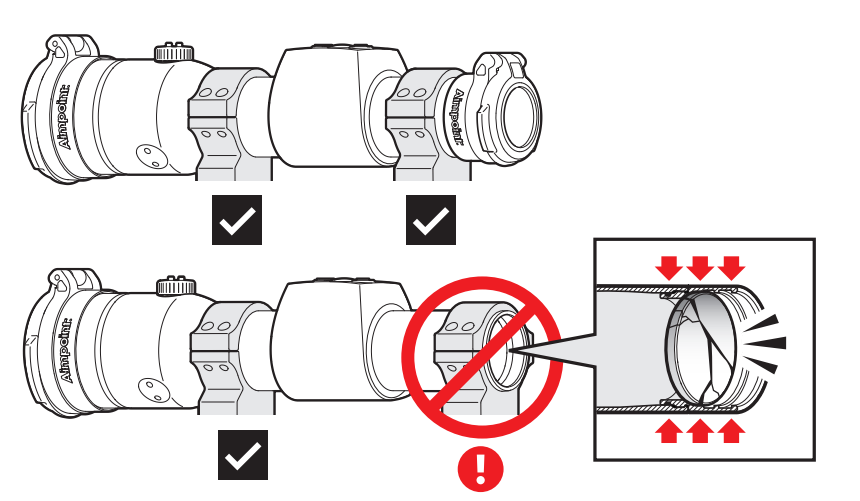
NOTE: In order to prevent damage to your sight and ensure a safe product installation, see Fig. 1.
- Finally, make sure that all screws of both rings are firmly tightened around the sight. The use of thread sealer is recommended.
NOTE: Over-tightening ring screws can cause damage to your sight.
- Complete the zeroing process (2.3).
Zeroing
CAUTION: Do not continue to adjust windage and elevation if you encounter resistance. The mechanism can break if over-adjusted.
- Open lens covers (8) and (9).
- Turn the sight on by pushing down the + or − buttons on the digital touch pad (1) until the red dot has a sufficient intensity to contrast against the target.
- To access elevation adjustment screw (5) and windage adjustment screw (6), remove the adjustment cap (4).
- The adjustment cap (4) or the tool (7A) must be used to turn the adjustment screws. Place the knobs on the adjustment cap (4) into the recesses on the adjustment screws (5) and (6).
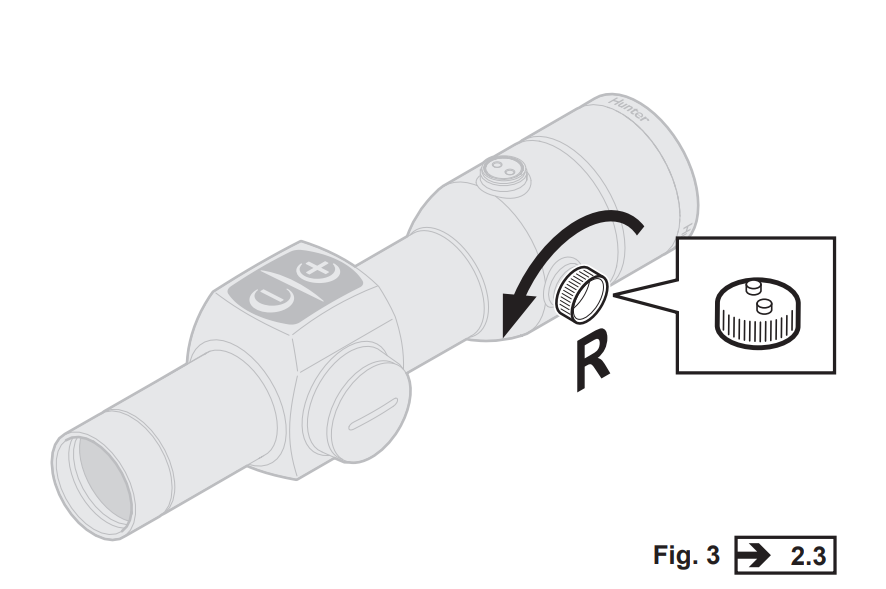
- Windage adjustments (See Fig. 3)
- To move the point of impact to the right, turn windage adjustment screw (6) counter clockwise.
- To move the point of impact to the left, turn windage adjustment screw (6) clockwise.
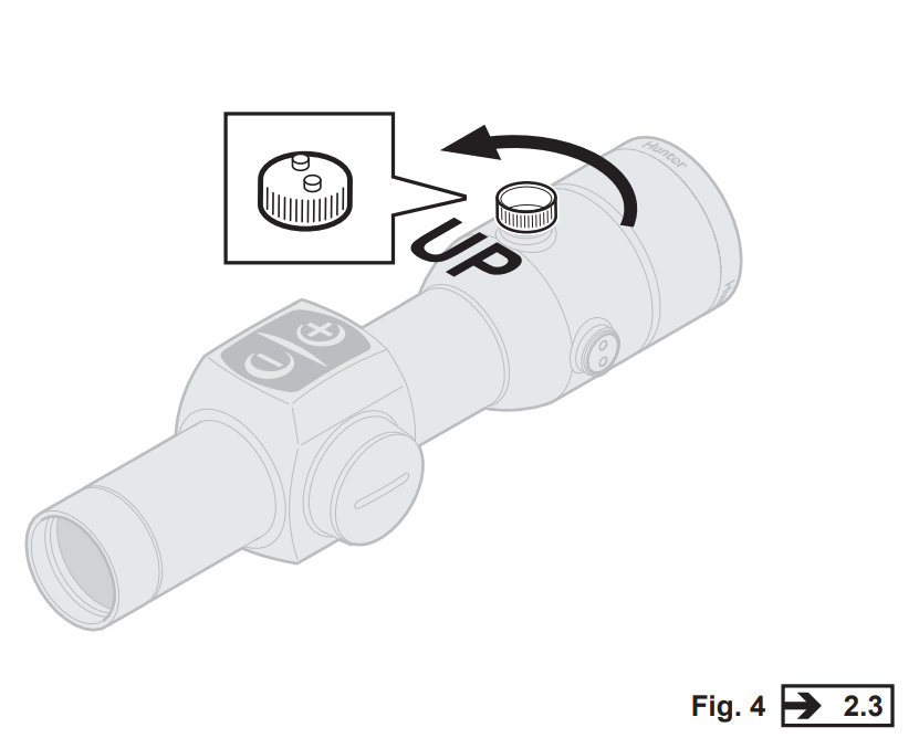
- Elevation adjustments (See Fig. 4)
- To move the point of impact up, turn elevation adjustment screw (5) counter clockwise.
- To move the point of impact down, turn elevation adjustment screw (5) clockwise.
NOTE: Each click of the adjustment screws (5) (6) corresponds to a 20 mm movement of the point of impact at 100 meters, (5 mm at 25 meters and 40 mm at 200 meters or 0.7 in at 100 yds).
- Confirm zeroing by firing at least three shots at a zeroing target. Check points of impact to confirm accuracy and repeat above procedure if required.
- After initial firing, ensure that the sight is securely installed on the weapon.
EXTREME CONDITIONS
Extreme heat (humid or dry): No special procedures required.
Extreme cold. Extreme cold might shorten battery life: Keep spare batteries in your inner pockets to keep them warm.
Salt air. No special procedures required:
Sea spray, water, mud and snow: Ensure that battery cap and the two adjustment screw caps are tight before exposing the sight to sea spray, mud and snow. Hand tighten only. Keep lens covers closed when sight is not being used. Clean lenses with lens soft cloth and wipe the sight dry as soon as possible after exposure to water, sea spray, mud or snow.
Dust storms and sand storms: Keep lens caps closed when sight is not being used.
High altitudes: No special procedures required.
CAUTION: The lenses should never be cleaned with fingers – always use a soft lens cloth. If no lens paper/cloth available:
- To clear away debris (sand, grass etc): blow away the dirt.
- To clean lenses: fog the lenses and dry them with a clean and soft piece of cloth.
TROUBLESHOOTING
The red dot does not appear or has disappeared
Clean contact surfaces in the battery compartment and verify that the battery (3) is working and that it is installed correctly. Verify that there is zero gap between the battery cap (2) and the battery compartment.
The sight is impossible to zero
If an adjustment screw (5) (6) is at its limit, check the alignment of mount and barrel. If point of impact is moving, check the stability of mount.
The red dot does not appear to be round
This is most likely the result of how your eye perceives the dot. Unload and make your firearm safe. Turn your sight on and look through the sight. Slowly rotate the sight. If the aberration in the shape of the red dot does not rotate along with the sight, it is how your eyes see the dot that is causing the irregularity. This effect
can be minimized by turning the brightness of the red dot just enough to match ambient lighting conditions.