

1 Overview
The Ventus is a high-performance binocular imaging system designed for both visible-light and thermal imaging applications. It features a fully integrated vision system combining a 15 mK ultra-high-sensitivity infrared detector with advanced 4K Ultra visible imaging, enabling exceptional target identification even in harsh weather conditions or environments with minimal thermal contrast. Equipped with precise laser rangefinding and switchable dual-band 850 nm / 940 nm infrared illumination, the Ventus ensures a clear and reliable field of view across day and night operations. With its exceptional versatility and intuitive ergonomics, the Ventus series redefines outdoor observation and situational awareness.

2 Features
- 640×512@12μm thermal imaging sensor
- NETD<15mK
- 4K Ultra CMOS sensor
- Integrated 1000m laser rangefinder
- 1600×1200, 0.5 inch AMOLED display
- Two replaceable 18650 batteries
- 850nm/940nm dual-band IR illuminator switch
- Picture in Picture
- Built-in 64 GB stroage
- EIS vision stability
- TSR algorithm
- Proximity sensor
- Adjustable interpupillary distance: 60-72mm
- Ergonomically designed hand grip
3 Specifications Ventus
| Model | Ventus 635L | Ventus 650L |
| Resolution | 640×512 | 640×512 |
| Pixel pitch | 12μm | 12μm |
| NETD | 15mK@300K | 15mK@300K |
| Spectral range | 8-14μm | 8-14μm |
| Objective lens | 35mm/F0. 9 | 50mm/F1.0 |
| Field of View/m@100m | 12.5°×10°/21.9×17.6 | 8.8°×7.0°/15.4×12.3 |
| Frame rate | 50Hz | 50Hz |
| Magnification | 2.6X-10.4X(4X) | 3.7X-14.8X(4X) |
| Detection range | 1800m | 2600m |
| Optical Module | ||
| Resolution | 3536×3536, 2μm | 3536×3536, 2μm |
| Field of view/m@100m | 8.1°×8.1°/14.14×14. 14 | 8.1°×8.1°/14.14×14. 14 |
| Objective lens | 50mm/F1.4 | 50mm/F1.4 |
| IR illuminator wavelength | 850nm/940nm switchable | 850nm/940nm switchable |
| Viewing range at night | 850nm:400m / 940nm:350m | 850nm:400m / 940nm:350m |
| Magnification | 4X-16X(4X) | 4X-16X(4X) |
| Image Display | ||
| Type | AMOLED | AMOLED |
| Resolution | 1600×1200 | 1600×1200 |
| Display size | 0.5 inch | 0.5 inch |
| Color palette | 6 | 6 |
| Eye relief | 20mm | 20mm |
| Exit pupil | 8mm | 8mm |
| Diopter | ±5D | ±5D |
| Interpupillary adjustment range | 60 mm to 72 mm | 60 mm to 72 mm |
| Image mode | Forest/Rainy | Forest/Rainy |
| TSR algorithm | Yes | Yes |
| Laser Rangefinder | ||
| Safety class | Calss 1 | |
| Wavelength | 905nm | 905nm |
| Range | 1000m | 1000m |
| Accuracy | ±1m | ±1m |
| Function | ||
| Photo/Video playback | Yes | Yes |
| Audio recording | Yes | Yes |
| Azimuth | Yes | Yes |
| Digital magnetic compass | Yes | Yes |
| Hotspot | Yes | Yes |
| Language | Multiple-language | Multiple-language |
| Storage | 64GB EMMC | 64GB EMMC |
| PIP | Yes | Yes |
| Heat track | Yes | Yes |
| Local album | Yes | Yes |
| OSD recording | Yes | Yes |
| Burn prevention | Yes | Yes |
| EIS | Yes | Yes |
| Power Supply | ||
| Battery type | Replaceable Li-ion battery (18650×2 | Replaceable Li-ion battery (18650×2 |
| Type-C power supply | 5V DC, 2A/Data transfer | 5V DC, 2A/Data transfer |
| Battery life | 6h | 6h |
| Environment | ||
| Working temperature | -20- +50℃ | -20- +50℃ |
| Protection level | IP67 | IP67 |
| Weight, g | 825±5 | 833±5 |
| Size, mm | 164(L)×127.6(W)×73(H | 164(L)×127.6(W)×73(H |
| Mounting adapter | 1/4-20-UNC | 1/4-20-UNC |
4 Packing List


5 Appearance 5 5.1 Product Size & Drawing


Appearance 5 5.2 Button Controls Description
| Icon | Annotation |  | S |  |
 | Power Switch | Power of | Standby | Power on |
| Icon | Annotation | Single Press | Long Press | Double Click |
 | Measure Button | Continuous measuring | / | PIP |
 | Capture Button | Snapshot | Record | / |
| Icon | Annotation | Thermal Vision | Night Vision | Night Vision |
 | Right Button Single Press | Image calibration | IR brightness | IR brightness |
 | Left Button Single Press | Color palette switching | Day & night mode switch | Day & night mode switch |
| Before entering the main menu | ||||
| Icon | Annotation | Left-Right | Short Press Push | Hold Forward |
 | Rotary Encoder | Digital zoom | Thermal & night | Entering main menu |
| After entering the main menu | ||||
| Icon | Annotation | Bidirectional | Short Press Push | Hold Forward |
| Rotary Encoder | Switch between menu items | Confirm / submenu | Exit |
5 Appearance 5 5.3 Buttons and Controls

- Eyecup
- Eyepiece
- Diopter adjustment ring
- Left button
- Power toggle switch
- Rotary encoder
- Focusing wheel for thermal sight
- Ranging button
- Capture button
- Lens cap
- Right button
- USB port
- Focusing wheel for visible light
- Proximity sensor
- IR illuminator toggle switch
- Removable IR illumination
- Battery compartment
6 Quick Start Guide
6.1 Battery Installation
The battery compartment is located on the left side of the device. Gently slide the latch and the battery cover will pop open. The device uses two 18650 batteries. The batteries are inserted in opposite polarities (one positive up and one reversed). After inserting the batteries, simply press the cover to close it.

6.2 Power On/Off & Standby Mode
Power on The orange toggle switch is located in the middle of the device and has three position indicators.
- When the switch is moved to the “ ”position, the device is powered on.
- S means standby (screen off)
- When the switch is moved to the “ ”position, the device is powered off.

When the switch is moved to the S position, the device enters standby mode and the screen turns off. To wake up the device again, move the switch
back to the“ ”position.
6.3 Auto Screen Of
Below the toggle switch, there is a proximity sensor used to detect whether an object is approaching, thereby controlling the OLED on/off state. When the user’s head comes within 3 cm of the proximity sensor, the OLED automatically turns on. Once the user moves away from the sensor, the OLED automatically turns off.This feature which is named with Proximity Sensor needs to be enabled in the settings; details will be explained in the Settings part.

6.4 Image Adjustment on Device
After turning on the device, first adjust the diopter (①) to ensure the OLED UI icons are clearly visible. Next, adjust the interpupillary distance (②) by sliding the eyepieces left or right until comfortable binocular viewing is achieved. When using the thermal imaging mode, adjust the focus using the left focusing knob (③) to obtain a clear image. When using the visible light imaging mode, adjust the focus using the right focusing knob (④) to obtain a clear image. A single forward push of the rotary encoder(⑤)switches etween infrared thermal imaging mode and visible light mode.
Two rotary control icons are displayed on the software user interface, one on the left and one on the right. Depending on whether the system is operating in infrared thermal imaging mode or visible-light imaging mode, the corresponding rotary control indicator is automatically highlighted to show the active control.
6.5 Thermal and Visible Light Mode Switching
After powering on the device, briefly push the rotary encoder forward once to switch between thermal mode and visible light mode. Push the encoder forward again to switch back.

6.6 Photo Capture & Video Recording
Press the Photo button once to capture a photo. Press and hold the Photo button to start video recording. All captured photos and recorded videos are saved in the device storage. Note: This function is available in both thermal
and visible light modes.

6.7 LRF Function
Press the Rangefinder button once to activate continuous laser ranging. A ranging cursor will be displayed on the screen. Align the cursor with the target by moving the device to measure the distance
Note: This function is available in both thermal and visible light modes.

6.8 PIP
Double-click the ranging button to enable the PIP (Picture-in-Picture) function. Note: The PIP function for thermal imaging and visible imaging modes is configured separately. It must be enabled in the main menu,PIP display modes details will be explained in the Settings part.

6.9 Thermal Image Quick Settings
6.9.1 Color Palette Switching
In thermal imaging mode, press the Left button once to switch the color
palette. Six color palette modes are available:

Color Palettes


6.9.2 Image Calibration
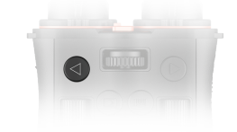
In thermal imaging sight, single-click the right button to calibrate the image.
6.10 Visible Light Image
6.10.1 Day Light Mode & Night Vision Mode Switching
In visible light mode, press the Left button once to switch the image mode between Daylight Mode and Night Vision Mode.

6.10.2 IR Illuminator Adjustment
In Night Vision Mode If the illuminator is required, move the illuminator switch to position I or II to turn it on
- I: 850 nm
- O: Off
- II: 940 nm
Then, press the Right button once to adjust the illuminator brightness.
A total of five brightness levels are available:
- 0(off)
- 1

- 2

- 3

- 4

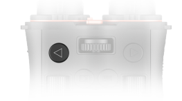
Please note: when the brightness level is set to 0, the fill light is turned off. In this state, switching to 850 nm or 940 nm cannot be observed on the device. If there is no response when switching wavelengths, please press the right button to adjust the fill light brightness level. In addition, the adjustment knob on the illuminator is used to control the beam focus and spread. Adjust it according to the actual operating conditions.

Note: If the illuminator is not required, it can be removed by loosening the fixing screw and detaching the illuminator from the device.

6.11 Power Supply
The battery can be removed and only charged separately using a charger.

7 Main Menu
All settings and controls in the main menu interface are operated using the rotary encoder. The following is a brief introduction to the operation methods:
- On the main interface, press and hold the rotary encoder forward for 2 seconds to enter the main menu.
- Rotate the encoder left or right to move the cursor and select the desired icon.
- Briefly push the encoder forward once to confirm or enter the next-level menu.
- When a parameter is selected for adjustment, rotate the encoder left or right to change the value, then push the encoder forward once to confirm and save the setting.
- Press and hold the encoder forward for 2 seconds to return to the previous menu or exit.

Thermal
Image Set

Thermal image ettings
after entering thermal
image settings , four adjustable parameters are available:

And two image modes are available and can be switched according to actual usage conditions:
- Forest
- Rainy

Day
Image Set

Day Image Set
After entering Day Image Set Four adjustable parameters are available:


PIP

PIP
The PIP function must be enabled in
the menu before it can be activated using
the buttons. After entering the settings
interface:
- Turn ON the switch

- Select the display mode: Daytime or Thermal
1:When the device is in single-spectrum PIP mode (CMOS + CMOS PIP / Thermal + Thermal PIP), the default PIP window is displayed at 4× agnification, and digital zoom applies only to the main image.
2:When the device is in multi-spectrum PIP mode (Thermal + CMOS PIP / CMOS + Thermal PIP), the PIP window displays the other channel at 1× by default, and digital zoom applies only to the main image.

WLAN

WLAN
After enabling WLAN function , the device Wi-Fi network can be found and connected to using a
mobile phone.
- Name:Ventus+Module+Serial number
- Password: 12345678
The Wi-Fi network name and password are set to default and cannot be modified.

Files

File Storage
After entering the File option two separate folders are available:
- Image
- Record
These folders store the photos and videos captured by the device, respectively. After entering a folder, a list of stored files will be displayed. Selecting an image or video allows user to perform operations such as viewing or deleting the file.

Setting

Setting-Palettes
In the Palettes settings , six color options are available for selection. Users can switch between them
according to actual operating conditions.
- White
- Black
- Red
- Green
- Golden
- Violet
Note: This function is only available in thermal imaging mode.
Setting

Setting-Correction
Image Calibration can be set to the following modes:
- Automatic
- Manual
In Automatic mode, a 10-second countdown prompt will be displayed before calibration is performed.

Setting-Audio
After enabling the Audio function , audio will be recorded ogether with video during recording.

Setting-OSD
After the OSD function  is turned off, no icons will be displayed on the main interface, allowing users to enjoy a more immersive viewing xperience. Users can configure this setting according to their personal preferences.

Setting-Tracking
When the Tracking function  is enabled, a cursor will appear on the screen. When a heat source target enters the field of view, the cursor will follow the heat source for tracking.

Setting-Unit
In the Unit settings  , users can switch between metric and imperial units according to their personal preference.

Setting-Anti-Burn
The anti-burn protection function
is enabled by default to protect the
device and prevent detector damage if it is accidentally aimed at the sun. When the protection is triggered, press any button to unlock the device screen.

Setting-Orient
When Orient is enabled, the main
interface will display three angles:
- Azimuth (center of the screen)
- Roll (left side of the screen)
- Pitch (right side of the screen) When using the device for the first time, gyroscope calibration
 is required. The calibration rocedure will be explained in Chapter 8.

Setting-OLED
OLED-Mode:
After entering the OLED settings ,
,
you can switch between modes:
- Day
- Night
OLED-Hue: Background color adjustment: Hue  Users can change the
OLED background color based on personal preference:
- Grey
- Blue
- Purple
- Red
OLED-Brightness: User can adjust the display
brightness of the OLED, the range is :
- 1-10

Blind Pixel
Note: Applicable only to infrared thermal imaging. Please follow the Blind Pixel steps below to erform bad pixel replacement:
- Put the lens cap on first.
- Tap Cancel to prevent accidental operation.
- Tap Replace repeatedly until the dead pixels are removed.
- Tap Save.

Setting-EIS
After the Electronic Image Stabilization function is enabled, the image can be effectively tabilized during high-magnification observation, providing a smoother and more stable viewing experience. Visible light mode only

Proximity Sensor
After this function is enabled, the device’s automatic screen-off feature will also be activated. If the main power switch is set to the standby position, this function will not take effect

FOV Sync
After this function is enabled, the fields of view of the dual channels will be automatically matched and adjusted in sync, ensuring image consistency when switching between channels. This effectively reduces the discomfort caused by channel witching and significantly improves overall viewing continuity and user experience.

Ballistic Calculator
After this function is enabled, you can input the corresponding parameters to calculate the bullet drop at a specified distance which measured by LRF, providing assistance for hunting and shooting. The calculated distance and bullet drop will be displayed in the upper right corner of the screen, and the user can switch their units.


System-Logo
Users can enable or disable the display of the ThermTec logo .
.

System-Time & Date
Users can modify the date and time  .
.
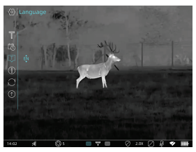
System-Language
Users can change the language
according to their needs.

System-Version
Users can view detailed device
information:
- SN
- Version
- ISPV

System-Reset After confirming Reset  , all settings will be restored to System factory defaults.

System-Update
Users can Update the device using the firmware corresponding to their device model series provided on the ThermTec official website. The details will be explained in Chapter 10
8 Digital Magnetic Compass Calibration
Before using the Orient function for the first time, the Digital magnetid Compass must be calibrated.
- Enter the Orient function and tap Calibrate. The calibration steps will be displayed on the screen.
- Tap Start, then follow the on-screen guidance symbols to move and rotate the device.
- The process takes 10 seconds


After calibration is completed, enable the function to display:
- Azimuth (center of the screen)
- Roll (left side of the screen)
- Pitch (right side of the screen)

9 Download“ThermTec 9 Outdoor”APP
You may download the“ThermTec Outdoor”APP through the QR code


10 Firmware Upgrade
The Ventus Series supports the ThermTec Outdoor APP, which allows real-time transmission of images and videos from the device to a smartphone or tablet via the device hotspot. The electronic version of this User Manual and the latest firmware can be downloaded from the ThermTec website: www.thermeyetec.com Firmware upgrades can also be performed via the ThermTec Outdoor APP.
Upgrading via APP
- Open the ThermTec Outdoor APP.
- After the device is connected, the APP will indicate if a firmware update is available.
- Before downloading the firmware, please turn on mobile data.
- After the firmware is downloaded and ready for upgrade, please turn off mobile data to ensure a stable upgrade process.
- Once the upgrade is completed, the device will automatically reboot.
Upgrading via PC
- Download the corresponding firmware upgrade package from the official website: www.thermeyetec.com.
- Connect the device to the PC using a Type-C cable.
- Copy the corresponding firmware update file to the device’s internal storage folder named “Storage”
- Push forward the rotary encoder 2s entering the main menu, then rotate the encoder and press to select the Update icon under System option, and the device will display an “Update” prompt.
- After completion, enter the Version menu to verify the firmware version.
- A detailed firmware upgrade instruction video is available on the official ThermTec channels.


11 Technical Inspection
A technical inspection of the device is recommended before use.
- Check the external appearance of the device. Ensure that there are no cracks in the housing.
- Check the condition of the lens and eyepiece. Ensure there are no cracks, oily marks, dust, or other contaminants.
- Check the image display. Ensure there are no dead pixels or abnormal lines on the screen. If any issues are found, please contact your dealer or point of purchase for replacement
Attention: Damage to the sensor caused by improper use or human factors is not covered by the warranty.
12 Maintenance
Maintenance should be performed at least twice a year and includes the following procedures:
- If the product does not work properly, please contact your dealer or the nearest service center. We shall not assume any responsibility for problems caused by unauthorized repair or maintenance.
- Make sure that the power has been disconnected before device teardown and repair by professionals.
- Check the optical surfaces of objective lens, eyepiece, rangefinder, etc. If necessary, remove dust and sand from the optics using tools and solvent designed especially for this purpose (it is preferable to use a non-contact method)
- If the equipment is used in a manner not specified by the manufacturer, the protection provided by the device may be impaired.
- Wipe the exterior surfaces of metal, plastic, and silicone parts with a clean and soft cloth. Do not use chemically active substances, solvents, etc. as these may damage the paint.
Using Environment
- Make sure the running environment meets the requirement of the device. The operating temperature shall be -20 °C to 50 °C , and the operating humidity shall be from 5% to 95%.
- DO NOT expose the device to high electromagnetradiation or dusty environments.
- DO NOT aim the lens at the sun or any other bright light.
- Place the device in a dry and well-ventilated environment.
- When any laser equipment is in use, make sure that the device lens is not exposed to the laser beam, or it may burn out.
- Avoid equipment installation on vibratory surface or places subject to shock (neglect may cause equipment damage).
- This equipment is not suitable for use in locations where children are likely to be present.
- This equipment is not suitable for use in locations where children are likely to be present.
Emergency
If smoke, odor, or noise arises from the device, immediately turn off the power, unplug the power cable, and contact the service center.
Laser

When any laser equipment is in use, make sure that the device lens is not exposed to the laser beam, or it may burn out. The laser radiation emitted from the device can cause eye injuries, burning of skin or inflammable substances. Before enabling the laser ranging function, make sure no human or inflammable substances are in front of the laser lens. Do not place the device where minors can fetch it. According to IEC 60825-1:2014, EN 60825- 1:2014+A11:2021, and EN 50689:2021, this laser product is classified as Class 1 laser product and consumer laser product.
Safety Information
These instructions are intended to ensure that user can use the product correctly to avoid danger or property loss. Please read all the safety information
carefully before using.
Transportation
- Keep the device in original or similar packagingwhile transporting it
- Keep all wrappers after unpacking them for future use. In case of any failure occurred, you need to return the device to the factory with the original wrapper. Transportation without the original wrapper may result in damage on the device and the company shall not take any responsibilities.
- Do not drop the product or subject it to physical shock. Keep the device away from magnetic interference.
Power Supply
- If a power adapter is provided in the device package, use the provided adapter only. If no power adapter is provided, ensure the power adapter or other power supply complies with Limited Power Source. Refer to the product label for the power supply output parameters.
- Make sure the plug is properly connected to the power socket.
- DO NOT connect multiple devices to one power adapter, to avoid over heating or fire hazards caused by overload
- The power delivered by the charger must be between min. 10 Watts required by the radio equipment, and max. 10.4 Watts in order to achieve the maximum charging speed.
Battery
- The device supports removable li-ion battery. The battery rated voltage and capacity is 3.6 V/3300 mAh
- CAUTION: Risk of explosion if the battery is replaced by an incorrect type. Replace with the same or equivalent type only.
- Batteries of improper size cannot be installed, and may cause abnormal shutdown
- Improper replacement of the battery with an incorrect type may defeat a safeguard (for example, in the case of some lithium battery types).
- Please purchase the batteries recommended by the manufacturer if necessary.
- The purchased batteries by users need to comply with the relevant international standards about battery safety (e.g. EN/IEC standards)
- Use the battery provided by qualified manufacturer. Refer to the product specification for detailed battery requirements.
- Dispose of used batteries according to the instructions.
- CAUTION: Risks of short circuit, fire, or explosion if the battery is damaged. Frequent use, dropping, impact, corrosion, or compression of the battery may cause damages including cracked casing, detached plates, or leakage of internal liquid or gas, etc.
- If the battery is damaged, stop using it immediately and dispose of it according to the instructions.
- Remove the battery if you do not use the device for a long time.
- For long-term storage of the battery, make sure it is fully charged every 2 months to ensure the battery quality. Otherwise, damage may occur.
- The built-in battery cannot be dismantled. Please contact the manufacture for repair if necessary
- Make sure the battery temperature is between 0°C to 50°C (32°F to 122°F) when charging
- Do not dispose of the battery into fire or a hot oven, or mechanically crush or cut the battery, which may result in an explosion.
- Do not leave the battery in an extremely high temperature or low air pressure environment, which may result in an explosion or the leakage of flammable liquid or gas
- Confirm there is no flammable material within 2 m of the charger during charging.
- DO NOT place the device with battery or the battery alone near heating or fire source. Avoid direct sunlight.
- DO NOT place the battery in the reach of children.
- DO NOT swallow the battery to avoid chemical burns.
- This product contains a coin/button cell battery. If the coin/button cell battery is swallowed, it can cause severe internal burns in just 2 hours and can lead to death.
- If the battery compartment does not close securely, stop using the product and keep it away from children
- If you think batteries might have been swallowed or placed inside any part of the body, seek immediate medical attention.
EGULATORY INFORMATION
This product and – if applicable – the supplied accessories too are marked with “CE” and comply therefore with the applicable harmonized European standards listed under the Directive 2014/53/EU(RED), Directive 2014/30/EU(EMC), Directive 2014/35/EU(LVD), Directive 2011/65/EU(RoHS).
 The full text of the EU declaration of conformity is available at the following internet address: https://www.thermeyetec.com/declaration-of-conformity/ Frequency Bands and Power (for CE). The frequency bands and transmitting power (radiated and/or conducted) nominal limits applicable to the following radio equipment are as follows: Wi-Fi 5GHz, 14 dBm For the device without a supplied power adapter, use the power adapter provided by a qualified anufacturer. Refer to the product specification for detailed power requirements. For the device without a supplied battery, use the battery provided by a qualified manufacturer. Refer to the product specification for detailed battery requirements.
 This product contains a battery and it is in conformity with the Regulation (EU) 2023/1542. The battery cannot be disposed of as unsorted municipal waste in the European Union. See the product documentation for specific battery information.
 The battery is marked with this symbol, which may include lettering to indicate cadmium (Cd), or lead (Pb). For proper recycling, return the battery to your supplier or to a designated collection point. For more information see: www.recyclethis.info.
 This product and – if applicable – the supplied accessories too are marked with “UKCA”and comply therefore with the following directives: Radio Equipment Regulations 2017, Electromagnetic Compatibility Regulations 2016, Electrical Equipment (Safety) Regulations 2016, the Restriction of the Use of Certain Hazardous Substances in Electrical and Electronic Equipment Regulations 2012.
 This product and – if applicable – the supplied accessories too are marked with “RoHS”and omply therefore the requirements of Directive 2011/65/EU on the restriction of the use of certain hazardous substances in electrical and electronic equipment (“RoHS recast”or“RoHS 2”).
 2012/19/EU (WEEE directive): Products marked with this symbol cannot be disposed of as unsorted municipal waste in the European Union. For proper recycling, return this product to your local supplier upon the purchase of equivalent new equipment, or dispose of it at designated collection points. For more information see: www.recyclethis.info.
Directive 2006/66/EC and its amendment 2013/56/EU (Battery Directive): This product contains a battery that cannot be disposed of as unsorted municipal waste in the European Union. See the product documentation for specific battery information. The battery is marked with this symbol, which may include lettering to indicate cadmium (Cd), lead (Pb), or mercury (Hg). For proper recycling, return the battery to your supplier or to a designated collection point. For more information see:www.recyclethis.info.