Products:
- Nightforce ATACR 5-25×56
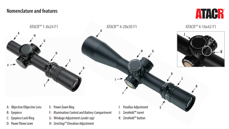
- Nightforce ATACR 4-16×42 F1 Compact tactical rifle scope
- Nightforce ATACR 5-25×56 F1
- Nightforce ATACR 7-35×56 F1
- Nightforce ATACR 4-16×50
- Nightforce ATACR 1-8×24 F1
- Nightforce ATACR 4-16×50 F1
- Nightforce ATACR 5-25×56 F1 + ERA-TAC one-piece mount, 34 mm
Mounting/Installation Considerations
There are many ways to mount and level a riflescope to a rifle system. Below are some considerations when mounting the riflescope to the rifle. Some may vary depending on rifle, mount and riflescope combination.
- If using a removable scope base, ensure base is solidly attached to receiver.
- Install mount(s) and bases per manufacturer’s specifications using proper torque.
- Avoid positioning the rings where they will contact the adjustments, objective bell or power zoom ring on the riflescope.
- Apply forward pressure to the mount(s) while tightening in place to keep the cross bolt in firm contact with the forward surface of the cross slot in the base.
- Set the riflescope to the highest magnification for mounting.
- Check for eye/head position when mounting, so that the riflescope is mounted in the best location for the various shooting positions behind the rifle.
- It is recommended to mount the riflescope with as much eye relief as possible on heavy recoiling rifles.
- For precision shooting, ensure the reticle and rifle are plumb to each other. Improper alignment creates sighting/impact errors that become magnified at distance.
Establishing a Sight-in Zero
An expedient way to save time and ammunition when zeroing a rifle is to bore sight the riflescope.
To Bore Sight
- Ensure that the rifle is completely unloaded.
- Remove the bolt and place the rifle on a stable rest.
- Looking through the bore from the action/receiver, center your target downrange so that it is floating in the center of the bore (high visibility target of 5-6″ at 50-100 yards is best).
- Adjust the elevation and windage adjustments until the reticle is centered on the target while the target is still centered in the bore.
WARNING!
To avoid permanent eye damage or blindness, do not look directly at the sun or other extremely bright lights through the riflescope.
To Zero
- After bore-sighting, proceed to fire three to five rounds of ammunition at the target.
- Calculate the difference between point-of-aim (POA) and point-of-impact (POI) with the reticle of the riflescope or a measuring device on the target.
- Adjust the elevation and windage adjustment to match the POA and POI.
- Fire three to five rounds of ammunition to confirm zero distance. Repeat adjustments until POA = POI.
- Follow instructions to zero elevation and windage dials.
- Operation in Extreme Conditions
The ATACR™ family of riflescopes has been designed and constructed to withstand heavy use in austere environments.
Temperature
Extreme heat: No additional procedures required.
Extreme cold: No additional procedures required.
NOTE: Adjustments may have more or less resistance than normal, and battery life may be shortened.
Conditions
Dust and sand storms: When riflescope is not in use, keep protective caps closed over glass lenses.
Salty air: No additional procedures required.
High altitude: No additional procedures required.
Immersion
Water, mud, snow: Ensure that adjustments are properly installed and screws are properly torqued. When riflescope is not in use, keep protective caps closed over glass lenses. Clean and dry riflescope as soon as possible after exposure.
Capped Elevation Adjustment
This Nightforce® ATACR™ 1-8×24 F1 features a low profile, capped elevation adjustment. (Figure 1) The elevation adjustment is waterproof and can be used without the cap. A trim ring is included to protect the cap threads if using as an external adjustment. Once you have established your zero, you can now reset the elevation dial to zero.
- While holding the adjustment dial, loosen the two set screws on top of the dial with a 5/64” Allen wrench. (Figure 2) The dial should now rotate freely, and you should not feel any clicks.
- Rotate the dial clockwise until it stops.
- Turn the dial counter-clockwise until the “0” on the dial is aligned with the zero-reference mark on the body tube. (Figure 3)
- While holding the dial, tighten both set screws to 4 inch-pounds. If no torque driver is available, tighten 1/8 turn past initial resistance.
- Dust cap may be placed over adjustment dial by turning clockwise until secure. (Figure 4)
Trim Ring Installation
- Remove outer cap by screwing counter-clockwise.
- Install trim ring by screwing on clockwise until snug against the body tube. (Figure 5)

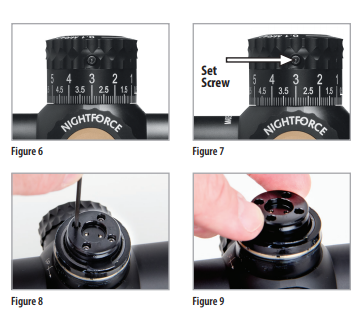
Many Nightforce® ATACR™ riflescopes feature an exposed, ZeroStop® elevation adjustment. (Figure 6) The ZeroStop® allows for a rapid return to zero, even after dialing for extended range shots. Once you have established your zero, you can now set the ZeroStop® and the elevation dial to zero.
- While holding the adjustment dial, loosen the two set screws on the side of the dial with a 5/64″ Allen wrench. (Figure 7) The dial should now rotate freely, and you should not feel any clicks. Remove the adjustment cap with an upward twisting motion.
- Loosen the four set screws of the upper clutch face but do not remove (Figure 8).
- Rotate the upper clutch face clockwise until it stops against the lower clutch face (Figure 9).
- Tighten the four set screws in an “X” pattern to 4 inch-pounds using the 3x tool. If no torque driver is available, tighten 1/8 turn past initial resistance.
- Reinstall the cap and turn the dial until the “0” on the dial is aligned with the zero-reference mark on the body tube.
- While holding the dial, tighten both set screws to 4 inch-pounds. If no torque driver is available, tighten 1/8 turn past initial resistance.
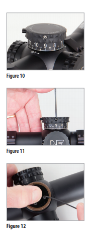
A correctly zeroed ZeroHold elevation adjustment will hold the turret in place at your zero position until the ZeroHold button is depressed. Additionally, the ZeroHold will allow 2 Mil-Radian of travel below zero.
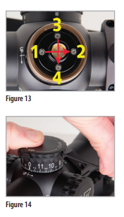
- With an established zero, dial 2 Mil-Radian below zero (Figure 10); if 2 Mil-Radian cannot be dialed below zero, see page 9 for Additional Travel Below Zero. While holding the turret in position, loosen the turret set screws on the dial with the 3X tool or a 5/64″Allen wrench (Figure 11). It should now rotate freely without any clicks and can be removed.
- On the exposed turret, use the T6 Torx bit on the 3X tool to loosen the four screws on the clamp wheels.
NOTE: Loosen but do not remove these screws. (Figure 12) - The clamp wheel should now rotate freely. Rotate the center clamp wheel counter-clockwise until it bottoms out.
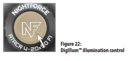
- While holding the clamp wheel in place, tighten the four screws with the T6 Torx bit to initial resistance, then tighten in an even “X” pattern to 2 inch-pounds (approximately 1/8 turn past snug). (Figure 13)
- Place the turret cap back on, turn the loose dial to where 10 Mil-Radian/2 Mil-Radian below zero is aligned with the zero-reference mark on the body tube. Push down to hold the turret in position. (Figure 14)
- While holding the dial in place, tighten the set screws to 10 inch-pounds. If no torque driver is available, use the 3X tool or 5/64″ Allen wrench and tighten 1/4 turn past initial resistance.
- Dial back to “0”, the ZeroHold button should engage and prevent rotation without depressing the button.
Additional Travel Below Zero (ZeroStop and ZeroHold)
If additional travel below zero is desired but the turret does not have adequate adjustment:
- While holding the turret in position, loosen the set screws on the dial with a 5/64″ Allen wrench. It should now rotate freely without any clicks and can be removed.
- On the exposed turret, loosen (but do not remove) the four screws on the clamp wheels.
- The clamp wheels should now rotate freely. Rotate the center clamp wheel counter-clockwise 1/4 to 1/2 turn.
- Torque the clamp wheel and reinstall the ZeroStop or ZeroHold turret cap based on the instructions on page 7 or 8.
Windage Adjustment
The windage adjustment on ATACR™ riflescopes is included with a protective, screw-on cap from the factory. (Figure 15) The windage adjustment is waterproof and can be used without the cap.
Once you have established your zero, you can now reset the windage dial to zero.
- While holding the adjustment dial, loosen the set screws on the outside of the dial (Figure 16) or the set screws on the edge of the dial (Figure 17). The dial should now rotate freely, and you should not feel any clicks.
- Rotate the dial until the “0” on the dial is aligned with the zero-reference mark on the body tube. (Figure 18)
- While holding the dial, tighten both set screws to 4 inch-pounds. If no torque driver is available, tighten 1/8 turn past initial resistance.
Trim Ring Installation
- Remove outer cap by screwing counter-clockwise.
- Install trim ring by screwing on clockwise until snug against the body tube. (Figure 19)

Diopter Adjustment
One user adjustable optical setting on all Nightforce ATACR riflescopes is the reticle/diopter adjustment. The diopter adjustment changes reticle focus to match the user’s eye prescription. If you wear vision correction when shooting, set this focus while wearing your corrective lenses.
NOTE: Nightforce® riflescopes are factory set (-3/4 diopter), so adjustment may not be necessary. If the reticle fades in and out of focus, or if the user experiences eye strain with extended shooting sessions, it is an indicator that the diopter may be out of focus.
- For scopes with parallax adjustment, set it to the infinity setting (∞). For most users, setting the riflescope at the highest magnification yields the best result.
- Grasp the eyepiece with one hand and the locking ring with the other and rotate the eyepiece counter-clockwise, loosening it from the lock-ring.
- Look through the riflescope at a light-colored background such as a white wall or overcast sky to eliminate background clutter that will distract your eye. Determine if the reticle is clear and in focus at the instant you look through the eyepiece and see the reticle (a snap sight picture).
NOTE: Staring at the reticle for more than a second will cause your eye to focus on the reticle, falsely indicating proper reticle focus. Look away for a few seconds and then retry repeatedly for best results.
- If the reticle is not crisp and well defined, move the eyepiece and re-check for focus. Best results are obtained by turning the eyepiece inward until the reticle is slightly blurred, then moving it outward until a sharp focus is obtained.
- Once the desired reticle focus is achieved, turn the lock ring clockwise while holding the eyepiece in place. Tighten the lock ring firmly.
NOTE: On some riflescopes, particularly those with 1x magnification, it is important to also check the reticle focus at a low magnification setting. Major adjustments from 0 diopter can create minor increases or decreases in magnification, causing slight distortions at low power. A diopter setting that is balanced between low and high magnification may be required to give the best results for your eye and the distances being viewed through the optic.

Power Throw Lever
Nightforce® ATACR™ riflescopes are equipped with an optional, integrated Power Throw Lever (PTL™). This feature is removable at the user’s preference. The PTL is designed to allow easy and rapid magnification changes; as well as provide a visual reference to the current magnification setting. To install the PTL™, first remove the flush black insert located in the power zoom ring with a 5/64″ hex key (Figure 29). Install the PTL by screwing it into the threaded hole in a clockwise direction. Tighten to snug with the 5/64″ hex key, but do not overtighten to avoid stripping the threads or hex key slot. (Figure 21)

Parallax Adjustment
Most ATACR™ riflescopes have parallax adjustment mechanisms. Parallax is the apparent movement of the reticle in relation to the target as the shooter moves his eye across the exit pupil of the riflescope. This condition is caused by the target and the reticle appearing on different focal planes within a riflescope. At longer distances, and higher magnification settings, significant sighting error can result if parallax is not removed. For best results we recommend checking for parallax, and removing if necessary, at each change in target distance.
Checking for and removing parallax
While keeping the rifle stable and looking through the riflescope at a specific point of aim on your target, a nod of the head up and down will quickly determine if parallax is present. When parallax exists, the reticle will appear to move even though the riflescope is stationary as the head is nodded up and down.
To remove parallax, adjust the parallax adjustment mechanism until the reticle remains stationary in relation to the target regardless of head movement.
NOTE: The accuracy of the distance is dependent on the user’s eye, the diopter setting, and the environmental conditions. Therefore, the distances engraved on the parallax adjustment are approximat.
Reticle Illumination (1-8×24)
The ATACR™ 1-8×24 riflescope is equipped with daylight visible, externally adjustable illumination. To turn on the illuminated reticle, simply rotate the external dial to your preferred intensity setting. There are “OFF” settings between each intensity adjustment, so that a user can turn off illumination at their preferred setting. Daylight illumination of the reticle is available at the higher intensity settings. Ambient light and environmental conditions will dictate the appropriate setting for desired visibility. Too much intensity in low-light environments can produce a flare effect on the reticle.
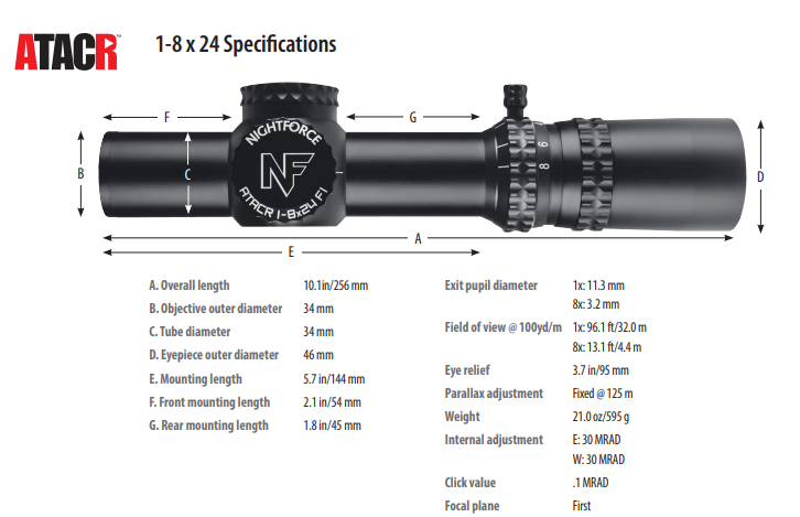
DigIllum™ Reticle Illumination
All Nightforce® ATACR™ riflescopes (except for 1-8×24) feature DigIllum™ digital illumination, including both red and green options. Reticle illumination is controlled by the tan-colored push button located in the center of the parallax adjustment. (Figure 22).
Turning the illumination on and off
To turn on your DigIllum™ illuminated reticle, simply press and release the illumination control located on the center of the side parallax adjustment. The reticle will illuminate to the last used intensity and color setting. To turn your DigIllum™ illuminated reticle off, press and hold the illumination control for 1-3 seconds and release.
Adjusting illumination intensity (brightness)
Once turned on, by repeatedly pressing and releasing the DigIllum™ illumination control you will change the intensity of the reticle. There are multiple intensity levels in the standard illumination mode. When the illumination reaches its minimum or maximum intensity, the reticle will flash three times. After reaching the minimum or maximum intensity, continuously pressing and releasing the illumination control will either increase or decrease the intensity away from the respective setting.
Selecting the reticle color
The DigIllum™ illuminated reticle allows the user to choose between red or green reticle illumination. By pressing the illumination control for about five seconds, the color will change from red to green or green to red.
Battery Replacement
The battery is located beneath the illumination adjustment (1-8×24) or parallax adjustment. The battery cover is removed by turning the illumination adjustment or parallax adjustment counter-clockwise until the cover comes off as shown in Figure 23 and Figure 24. Replace depleted batteries with an Energizer CR2032 or equivalent. Install the battery with the positive (+) side up. (Figures 24 and 25). Turn off the illumination when not in use to prevent depletion of the battery.

Riflescope Maintenance
With proper care, a Nightforce® riflescope will provide many years of dependable service. Be sure to use lens covers whenever you are not using your riflescope.
Cleaning Riflescope Exterior
Clean the riflescope body with a clean cloth, lightly moistened, with clean water or rubbing alcohol. Do not use strong solvents or gun cleaner as they can destroy lens coatings. While cleaning your rifle, be sure to protect your riflescope’s lenses by installing the covers that came with the riflescope. In the event of submersion in mud, sand, dirt or salt water; irrigate the outside of the riflescope with clean water to remove encrusted material and salt. Wipe the outside metal surfaces dry with a soft cloth.
Cleaning Riflescope Lenses
We recommend using a Nightforce® cleaning kit for lens cleaning. The kit contains an ultrasoft brush, microfiber cloth and cleaning solution. With the lens facing down, to allow debris to fall away, remove loose dirt and dust with lens brush. If there is grit stuck to the lens, irrigate the surface with distilled water and rub off with cleaning swabs. Using a soft, clean, lint-free cotton swab or lens cleaning cloth, clean the lens starting in the center and working to the outside in a circular motion. Make only one pass to the edge where the glass meets the metal. Once you reach the edge of the lens do not re-use that swab as it will contain abrasive grit that can scratch the surface. Start over in the center with a new swab and repeat the process until the glass is clean. Use a very small amount of cleaning solution if necessary and to prevent streaks.
Long Term Storage
If the riflescope will not be used for an extended period, remove the battery and store separately. Keep the riflescope in a cool, dry, dust-free location with lens covers closed.


Limited Lifetime Warranty
We are proud to back the Nightforce ATACR™, NX8, B.E.A.S.T.™, Benchrest, Competition™, NXS™ and SHV™ families of riflescopes with a transferable Limited Lifetime Warranty. The warranty covers mechanical defects in materials and workmanship in the optical and mechanical components of Nightforce riflescopes. In the event of a defect in materials or workmanship that is covered by this warranty, we will either repair the riflescope or replace it at no charge, with a comparable product at our discretion.
Exclusions to this warranty include intentional or accidental damage, abuse, misuse, unauthorized modifications or repairs, and improper mounting. This warranty does not cover any consequential or incidental damages resulting from the inability to use the riflescope. Any serial number obliteration or alteration on the product will void the warranty. SHV™ models maintain waterproof integrity with their protective caps installed.
To ensure warranty coverage, please register online or fill out completely and mail in the provided warranty card found in the back of the owner’s manual, along with a copy of the sales receipt. The warranty begins on the date the product was purchased by the original owner. The optical and mechanical components are covered without time limitations. The riflescope’s electronic components are covered for a period of three years.
This warranty gives you specific legal rights, and you may also have other rights which vary from state to state. Some states do not allow the exclusion or limitation of incidental or consequential damages, so the above limitations or exclusions may not apply to you. Some states do not allow limitations on how long an implied warranty lasts, so the above limitations may not apply to you.
Before sending a riflescope in for service, please call Nightforce Optics, Inc. at the number below, to determine if the problem can be resolved without sending us the product. All returns must be accompanied by a Return Merchandise Authorization (RMA) number. Failure to do so can result in lost merchandise and/or severely delayed service time.
- Remove any mounting rings or accessories other than dust covers and the original sunshade.
- Record and keep on hand the serial number.
- Include with the riflescope a detailed description of the defect(s), the RMA number, your name, phone number and the address you wish the riflescope returned to.
- Place the boxed or protectively wrapped riflescope in a well-padded outer box insured for replacement value and send it shipping prepaid, to the appropriate address below.
Write the RMA number on the outside of the package.
Be sure to register your warranty at www.NightforceOptics.com/WarrantyRegistration
U.S.A. & Canada:
Nightforce Optics
Attention: Service Dept.
336 Hazen Lane
Orofino, Idaho 83544
tel 208.476.9814
fax 208.476.9817
www.NightforceOptics.com
International:
Nightforce Optics
Attention: Service Dept.
11 Manton Street
Hindmarsh, SA 5007 Australia
tel +61 (0)8 8440 0888
fax +61 (0)8 8346 0504
www.NightforceOptics.com