
ACCESSORIES


THERMAL SIGHT FEATURES

TECHNICAL SPECIFICATIONS
| MODEL | 50mm |
| Detector | |
| Resolution | 400×300 |
| Pixel Size | 17µm |
| Optical properties | |
| Focal length | 35mm F1.2 |
| Focusing | Manual Focus |
| FOV | 10.6°×8.0° |
| Imaging | |
| Frame Rate | 50Hz |
| Digital Zoom | 2x, 4x |
| Display | |
| Screen | 1024×768 Color OLED |
| Color Palletes | Black hot, white hot, red hot, green hot |
| Optical Magnification | 1x |
| Power | |
| Battery Type | 2x CR123/ICR 16340 |
| Working Time | ≥3 hours |
| Interface | |
| 7-pin LEMO | for external USB power (included) |
| Video Output | 7-pin LEMO (optional) |
| External Connection | Picatinny rail |
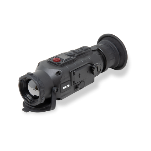
Lens
This guide is applicable to multiple lens series. The illustration shows only one of the lens models.
Focusing Ring
After the thermal imager is powered on, the image may be blurred when the distance to the observed target changes. The lens focusing ring should be turned to refocus until the target image is clear.
Lens Cover
Please cover the lens cap to protect the lens when the product is not in use!
External Interface
Through the external interface a USB cable can be connected to an external power source. The output specification of the external power supply should be 5V2A.
Video Cable
The external interface port can be used to attach a video cable providing output to an external monitor and external power at the same time.
Battery Cover
The cover provide access to the battery compartment. The thermal imager is powered by two (2) CR123 batteries.
Eyepiece
The eye mask, external eyepiece and adapter rings accessories are attached to the eyepiece.
Buttons
| BUTTONS | DEVICE CURRENT STATUS | SHORT PRESS | LONG PRESS |
| Power Button | Power Off | / | Power On |
| Power On | Calibration | Display Off/ Power Off | |
| Display Off | Display On | / | |
| No Display in Menu Bar | Switch to Zoom Mode | / | |
| Display in Menu Bar | Upward Switching Options | / | |
| Change Parameter Value | / | ||
| No Display in Menu Bar | Switch to Scene Mode | Enter Main Menu | |
| Display in Menu Bar | Enter the Sub-menu | Exit menu bar/ back to the previous menu | |
| Select Option/ Parameter Value | Exit menu bar/ back to the previous menu | ||
| No Display in Menu Bar | Switch to Color Palettes Mode | ||
| Display in Menu Bar | Downward Switching Options | / | |
| Change Parameter Value | / |
Power Button
To start the thermal sight imager, press the Power Button until the start up image is displayed.
Power-Off
To manually power off the thermal imager, hold the Power Button down until you see the power-off progress bar and the unit is powered off.
Auto Power-Off
Time for auto power-off can be set and if no operation is carried out within the time, the thermal imager will be powered off.
Display off
Hold the Power Button down to display the shutdown progress bar. Before the progress bar is complete, release the power button to cancel the shutdown and turn the display off.
Display on
In display off mode, press any key to turn the display on.
Calibration
Press the power On/Off Button when power is on the menu screen is off, to complete the calibration (except the automatic calibration).
Zoom-In
When power is on and the menu is not called out, short press the Up Button to switch from 2X/4X zoom.
Scene Modes
When power is on and the menu screen is off, short press M Button in turn to switch the scene modes from Enhance to Highlight to Nature.
Color Palette Modes
When power is on and the menu screen is off, press the Down Button to switch the pseudo-color modes of white hot, black hot, red hot, green hot.
- White hot – Objects at relatively high temperature are displayed as white or light grey.
- Black hot – Objects at relatively high temperature are displayed as black or dark grey.
- Red hot – Objects at relatively high temperature are displayed as red.
- Green hot – Displayed as a night vision image.
Menu
When power is on and the menu screen is off, press the M Button for two seconds to enter the main menu. When power is on and the menu is visible, press the M Button, to exit the menu bar or back to the previous menu.
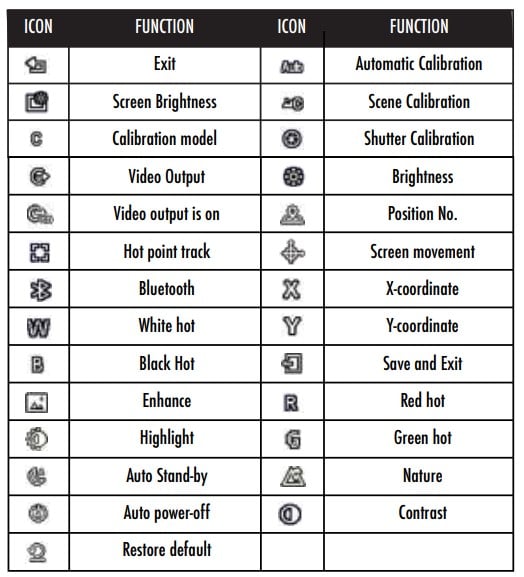
Icon Function
- Exit – To exit the menu bar.
- Screen brightness – To adjust the screen brightness from level 1 – 10.
- Calibration model – To set one of three settings: automatic calibration, scene calibration or shutter calibration.
- Video Output – To open/close video output. When the video output is on, the icon will be displayed in the lower right corner of screen.
- Hot point track – When hot point track is on, the switch can be set so the cursor will track the point with the highest temperature in the scene.
- Bluetooth – When Bluetooth is on, it will search and connect to a Bluetooth remote controller. Once connected, all the button functions (except power on/off function) on the thermal imager can be controlled by the Bluetooth remote controller. • Bluetooth on – “Bluetooth is searching…” appears and then quickly disappears, while the Bluetooth icon flickers.
- Successful Bluetooth connection – “Bluetooth
connection success” appears and then quickly
disappears, while the Bluetooth icon displays
all the time. - Bluetooth connection failure – “Bluetooth
connection failed” appears and then quickly
disappears, and the Bluetooth icon disappears. - Note – Bluetooth remote controllers are optional
accessories.
- Successful Bluetooth connection – “Bluetooth
- Auto stand-by – Time for auto stand-by can be set and if no operation is carried out, it will automatically enter stand-by mode .
- Auto power-off – Time for auto power-off can be set and any operation will stop it from turning off automatically.
- Restore default – To restore all the factory settings, select “Yes”. Select “No” to keep all current settings.
Note – After the default values are restored, the device will power off automatically. A manual restart is required for the change to take effect. - Contrast – The image contrast can be adjusted from level 1 – 10.
- Brightness – The image brightness can be adjusted from level 1 – 10
Note – The values of contrast and brightness adjustment are saved under the currently selected scene mode. - Position No. – Three groups of OLED screen position data can be saved. Each group of screen positions can be adjusted independently. Please select the position number to be adjusted before using the screen movement function.
- Screen movement – The optical axis of the equipment has been calibrated before delivered, with screen center coordinates (0, 0). If the optical axis shifts during use, you can use this function to realign the image.
Note – The screen movement is an auxiliary function. Please use it when necessary.
BATTERY INDICATOR
When the thermal imager is powered on, the battery indicator will display in the upper right corner of the screen. The green bar on the battery indicator indicates the maining capacity.

- After the power is on and a real-time image appears, the previous battery capacity levels will be displayed in the upper right corner of the screen.
- Note:
- Replace the battery when the power is low!
- When using a rechargeable battery, the battery indicator will remain on the full level for a longer time.
Storage and Maintenance
When the thermal imager will be not used for a long time, store in a dry, well-ventilated environment and charge the thermal imager at least four hours every two months during the storage
The infrared lens of the thermal imager is coated with an anti-reflection film. Clean the lens only when dirt or smudges are present. Frequent scrubbing may damage the lens coating.
To clean non-optical surfaces of the thermal imager, do not scrub with chemical solvents or cleaners. On exterior surfaces, wipe with a soft and dry microfiber cloth.
Warranty
The Burris Thermal Clip On products are covered by Limited Warranty and Burris will repair or replace your product if it is defective. Do not disassemble the thermal imager as this will void the warranty. Contact your nearest Burris dealer for assistance.
For detailed warranty information scan the QR codes below.
