
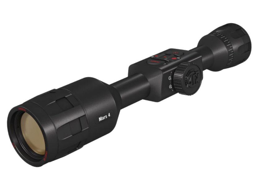
The most technologically advanced thermal vision smart scope is back, and now more improved than ever before . Improving on the thermal sensor technology, ATN is proud to introduce this 4th generation of Smart HD Thermal Rifle Scopes, with a dual core thermal sensor.
This new line of thermal scopes combines the classic features that set ATN apart from the competition, with new capabilities unique to this line. These scopes combine aspects like recoil activated video, one shot zero and ultralow power consumption, dual stream video (record and stream at the same time), and a new ultra-sensitive next generation thermal sensor which lets you view and record at high resolution.
The Mars 4 thermal scope features a suite of applications, like a built in ballistics calculator. Plus, it features recoil resistant components and an expandable MicroSD slot that lets you record up to 64 gigabytes of photo and video, and a new classic ergonomic Mars series design.


FEATURES

BALLISTIC CALCULATOR

RECOIL ACTIVATED VIDEO (RAV)

E-COMPASS

DUAL CORE PROCESSOR

SMART RANGE FINDER

SHARE ON SOCIAL MEDIA

ONE SHOT ZERO

ULTRA LOW POWER CONSUMPTION

PROFILE MANAGER
SPECIFICATIONS
| Mars 4 384 1.25 – 5x | Mars 4 384 2 – 8x | Mars 4 384 4.5 – 18x | Mars 4 384 7 – 28x | Mars 4 640 1 – 10x M | Mars 4 640 1.5 – 15x | Mars 4 640 2.5 – 25x | Mars 4 640 4 – 40x | |
| Item # | MS4K3819 | MS4K3825 | MS4K3850 | MS4K3875 | MS4K6419 | MS4K6425 | MS4K6450 | MS4K6475 |
| Sensor | Gen 4 384×288, 60 Hz | Gen 4 384×288, 60 Hz | Gen 4 384×288, 60 Hz | Gen 4 384×288, 60 Hz | Gen 4 640×480, 60 Hz | Gen 4 640×480, 60 Hz | Gen 4 640×480, 60 Hz | Gen 4 640×480, 60 Hz |
| Magnification | 1.25 – 5x | 2 – 8× | 4.5 – 18× | 7 – 28× | 1 – 10× | 1.5 – 15× | 2.5 – 25× | 4 – 40× |
| Field of view, degrees | 16×12.5 | 12×9.5 | 6×4.7 | 5×3.8 | 32×25 | 24×19 | 12.5×9.7 | 8.3×6.2 |
| Core | ATN Obsidian IV Dual Core T | ATN Obsidian IV Dual Core T | ATN Obsidian IV Dual Core T | ATN Obsidian IV Dual Core T | ATN Obsidian IV Dual Core T | ATN Obsidian IV Dual Core T | ATN Obsidian IV Dual Core T | ATN Obsidian IV Dual Core T |
| Micro Display | 1280×720 HD Display | 1280×720 HD Display | 1280×720 HD Display | 1280×720 HD Display | 1280×720 HD Display | 1280×720 HD Display | 1280×720 HD Display | 1280×720 HD Display |
| Eye relief | 90 mm | 90 mm | 90 mm | 90 mm | 90 mm | 90 mm | 90 mm | 90 mm |
| Video Record Resolution | 1280×960 @ 30/60 fps | 1280×960 @ 30/60 fps | 1280×960 @ 30/60 fps | 1280×960 @ 30/60 fps | 1280×960 @ 30/60 fps | 1280×960 @ 30/60 fps | 1280×960 @ 30/60 fps | 1280×960 @ 30/60 fps |
| Ballistic Calculator | Yes | Yes | Yes | Yes | Yes | Yes | Yes | Yes |
| WiFi Streaming, Gallery, & Controls) | iOS & Android | iOS & Android | iOS & Android | iOS & Android | iOS & Android | iOS & Android | iOS & Android | iOS & Android |
| Bluetooth | Yes | Yes | Yes | Yes | Yes | Yes | Yes | Yes |
| 3D Gyroscope | Yes | Yes | Yes | Yes | Yes | Yes | Yes | Yes |
| 3D Accelerometer | Yes | Yes | Yes | Yes | Yes | Yes | Yes | Yes |
| E-Barometer | Yes | Yes | Yes | Yes | Yes | Yes | Yes | Yes |
| Smart Range Finder | Yes | Yes | Yes | Yes | Yes | Yes | Yes | Yes |
| RAV (Recoil Activated Video) | Yes | Yes | Yes | Yes | Yes | Yes | Yes | Yes |
| Electronic Compass | Yes | Yes | Yes | Yes | Yes | Yes | Yes | Yes |
| Smooth Zoom | Yes | Yes | Yes | Yes | Yes | Yes | Yes | Yes |
| Reticles | Multiple Patterns & Color Options | Multiple Patterns & Color Options | Multiple Patterns & Color Options | Multiple Patterns & Color Options | Multiple Patterns & Color Options | Multiple Patterns & Color Options | Multiple Patterns & Color Options | Multiple Patterns & Color Options |
| Microphone | Yes | Yes | Yes | Yes | Yes | Yes | Yes | Yes |
| MicroSD card | 4 to 64 Gb | 4 to 64 Gb | 4 to 64 Gb | 4 to 64 Gb | 4 to 64 Gb | 4 to 64 Gb | 4 to 64 Gb | 4 to 64 Gb |
| USB, type C | Yes | Yes | Yes | Yes | Yes | Yes | Yes | Yes |
| Mount | 30 mm Standard Rings (included) | 30 mm Standard Rings (included) | 30 mm Standard Rings (included) | 30 mm Standard Rings (included) | 30 mm Standard Rings (included) | 30 mm Standard Rings (included) | 30 mm Standard Rings (included) | 30 mm Standard Rings (included) |
| Battery life (Li-ion) | 18 + hrs | 18 + hrs | 18 + hrs | 18 + hrs | 16 + hrs | 16 + hrs | 16 + hrs | 16 + hrs |
| Waterproof rating / IP rating | Weather resistant | Weather resistant | Weather resistant | Weather resistant | Weather resistant | Weather resistant | Weather resistant | Weather resistant |
| Smart Mil Dot Value Range | 4.0 – 10 | 4.0 – 10 | 2.0 – 10 | 1.0 – 10 | 4.0 – 10 | 4.0 – 10 | 2.0 – 10 | 1.0 – 10 |
| Human Detection Range | 750 | 960 | 1800 | 3000 | 830 | 1050 | 1950 | 3300 |
| Human Recognition Range | 335 | 480 | 720 | 1320 | 350 | 530 | 800 | 1450 |
| Human Identification Range | 205 | 300 | 430 | 720 | 225 | 330 | 475 | 800 |
| Dimensions | 13.1”x3”x3” / 332x76x76 mm | 13.5”x3”x3” / 343x76x76 mm | 13.8”x3”x3” / 351x76x76 mm | 14.8”x3”x3” / 375x76x76 mm | 13.1”x3”x3” / 332x76x76 mm | 13.5”x3”x3” / 343x76x76 mm | 13.8”x3”x3” / 351x76x76 mm | 14.8”x3”x3” / 375x76x76 mm |
| Weight | 1.93 lb / 0.88 kg | 2.03 lb / 0.92 kg | 2.2 lb / 1.0 kg | 2.35 lb / 1.06 kg | 1.93 lb / 0.88 kg | 2.03 lb / 0.92 kg | 2.2 lb / 1.0 kg | 2.35 lb / 1.06 kg |
| Warranty | 3 years | 3 years | 3 years | 3 years | 3 years | 3 years | 3 years | 3 years |
PREPARING THE DEVICE
UNPACKING
The following steps must be performed before using the device:
- Open packaging box, remove Mars 4 and check the contents
- Eyecup
- Standard rings (2 pcs.)
- L-shape ring
- Scope Cover
- USB-C cable
- QSG
- Manual
- Cloth
- Make sure that nothing is missing.
- Inspect the device for damage to optical surfaces, body, eyecups, operation buttons, etc.
- Ensure that all optical surfaces are clean and ready for use.
NOTE
If any accessories are missing or broken contact ATN Europe LTD’s Customer Service at [email protected].
CHARGING THE DEVICE
The device is equipped with a USB (type C) port. You will find it under the rubber cap on the right side of the device (caps are marked with appropriate icon). We have included a USB (type C) charging cable with your scope. Plug the cable into a USB wall charger that has an output of 2 amps (Wall Charger not included). Charge your scope for 6 hrs using a 2A USB wall charger. Note using a wall charger with lower amperage will take longer to charge your scope.
- Recommended charger is 2A USB charger.
- Battery charging time (from 0 to 100%) is 6 hours with 2 A USB charger.
- Battery run time is 16 hours on a single charge.
MICRO SD AND USB C PORTS
The device is equipped with a microSD Card and USB (type C) ports. You can find them under the rubber caps on the right side of the device (we marked the caps with appropriate icons). To open the rubber port cover, gently lift the rubber cover and move it out of the way.
NOTE
Make sure that the device is turned off before inserting the formatted micorSD Card into its assigned port.
- Always format a new microSD card before using.


- Insert microSD card as shown.
- Use a thin object (small coin, paper clip) to lock the microSD card in place after inserting it into the slot.
- Return the cover to its original position.
NOTE
There is only one correct direction to insert the microSD Card. Do not force the microSD Card into the port doing so may cause damage to both the scope and the card itself
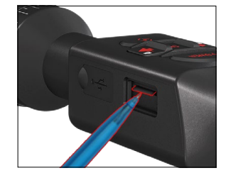
To remove the microSD Card from the port, push the card slightly in using the same thin object you did before. When the card pops up a few millimeters, pull the card out with your fingers or tweezers.
NOTE
If you are going to record video, the microSD Card should be a Class 10 (10 Mb/ sec) or faster and have capacity from 4 to
64 Gb that is an HC type SD card.
FIRMWARE UPDATE
Before operating your device, update the firmware to the latest version. All firmware updates can be found on at https://www.atneu.com/firmware. To receive a notification concerning new firmware updates, please register your device on our website. An email notification will be sent when a new firmware update becomes available. To update the firmware you will need a microSD Card and fully charged internal battery.
NOTE
In the event of a power failure during an update, the device may crash. This will corrupt the system files and the device will need to be sent back to the ATN factory for service. To ensure your zero coordinates are not lost, write down your zero coordinates before continuing to update the firmware!
Update the new firmware as follows:
- Download the ***.bin file and copy to your microSD Card — root directory.
- Insert the card into the scope.
- Turn ON the scope.
- In the “Firmware Update” dialog box select “Yes” to start the update.
- When the update counter reaches “100%” the device will automatically restart.
- Once the device is powered up it will enter self configuration mode.
- After completing it will automatically restart.
- Motion Sensing platform will be configured when first turned on.
- Once the Firmware update completes, please do a factoryreset before using the product.
- Please delete the Firmware file off of the microSD card after the process is complete. Or the system will try to update the Firmware every time you turn the scope on.
NOTE
If the device does not restart within 30 seconds, press and hold the power button for 15 seconds and the scope will turn off.

ON/OFF
To TURN ON the device press and hold the POWER button until you see the ATN splash screen. To TURN OFF the device press and hold the POWER button, until the dialog box. “Shut down the device?” appears. Choose “Yes” to turn off.
If the scope freezes or stops responding to the control panel. Press and hold the Power button for 15 seconds to reboot the scope.

USING YOUR KEYPAD AND SCROLL WHEEL
The KEYPAD is programmed to be used in two different ways:
- Short and Quick Taps — used for most functions and to get around the menu.
- Press and Hold — designed to be used in the following situations — ON/ OFF, SHORTCUT MENU.
- You can use the Power and Function buttons in System Menu as Up and Down buttons.
- The Scroll Wheel is used to magnify your target from the Home Screen, or during the zero in process.

NOTE
Using LEFT or RIGHT buttons in the Menu. You can quickly choose Exit Shortcut from any position. Use the Function Button from any menu screen to exit to the Home Screen by pressing and holding down the Function button for a few seconds.
FOCUSING
DIOPTER ADJUSTMENT
By rotating the Diopter Adjustment Ring you will achieve optimal sharpness for your vision. Look through the eyepiece while focusing on the reticle and widgets on the screen.
NOTE
Once the Diopter Adjustment is set to your liking, adjustment will not need to be performed unless another user altered the focus for their needs.


DISTANCE FOCUS
Rotate the Adjustment Ring, as neces- sary, to achieve the proper focus at various distances.
MOUNTING YOUR SCOPE

The Mars 4 has a 3.5-inch eye relief, and can be mounted using 30 mm mounting rings. ATN has provided two standard rings and one L shape ring. The L shape ring is for those instances when you need extra eye relief for certain rifles. First, choose your preference of rings and position and mount the bottom portions of your rings to your rail for optimal eye relief. Place the scope on the bottom half of the rings you just mounted, verifying you have sufficient eye relief for your platform. Place the top portion of your ring over the mounted bottom portion, make sure the holes align and the screws turn easily. Apply equal torque to all screws with the provided Allen wrench. Make sure your rings are tight on your rifles rail and will not come loose due to recoil.
For mounting the Mars 4 on the weaver rail:
- Loosen the fixing screws on the sides of the mounting rings
- Place the rifle scope on the weaver rail so that the projection of the rail, which is in the base of the ring, enters the recess in the rail.
- Tighten the fixing screws of the mounting rings.
NOTE
Please do not over tighten the Fixing Screws when attaching the rings to your rail, we recommend using 38 in-lbs.
CAUTION!
Be sure your weapon is not loaded. Use safe weapon handling proce- dures at all times.
COMPASS CALIBRATION

When the compass needs to be calibrated, the word “CAL” appears instead of the Compass Scale. To calibrate rotate the device on three axis rotation, as pictured on the left.
NOTE
After calibrating the device please remember that the compass will work best when holding the Mars par- allel to the ground.
Other possible abbreviations:
- ERR — an error was detected;
- SMF — your device is under Strong Magnetic Field;
- UPD — your firmware needs to be updated.
INTERFACE
HOMESCREEN
The first screen you’ll see after turning on the device is the Homescreen. It consists of Scales, Status Bar icons and different Information Widgets.

SCALES
- The E-Compass Scale shows yaw angle based on e-Magnetometer data.
- Roll Scale shows the rifles cant based on internal 3D Gyroscope.
- Pitch Scale shows rifle inclination based on internal 3D Gyroscope.
STATUS BAR
Displays information about the current state of the system. Icons that are inactive become invisible when not in use, and only the important information will appear.
- Battery — shows how much energy is left in the system.
- Micro SD Card — shows the presence or absence (red icon) of memory card.
- Ballistic Calculator, Bluetooth, and WiFi — shows when the function is enabled.
WIDGETS
Interface elements will appear as widgets that will provide access to useful information. There are several types of widgets:
- icons without value are used for mode displaying (Photo and VideoModes);
- only numerical value (Detailed Roll and Pitch Values);
- icons with a numerical value: Range, Zoom, Reticle Correction, Wind Speed.
- Photo Preview appears at the bottom of the Homescreen, after the photo is taken.


Display widgets can be disabled from the System Settings. To enter System Settings you should click the OK button  from Homescreen to access the Shortcut Carousel. Select the wrench icon with RIGHT or LEFT buttons
  and push the OK button to enter the System Settings menu. Select the Display tab with RIGHT button
  and choose subcategory Display Widgets with the Scroll Wheel or Keypad buttons
  Press the OK button to select the Display Widgets. Use the Scroll Wheel or Keypad buttons to change from Extended to Minimal.
MAIN OPERATIONS
 ZOOM LEVEL
Use the Scroll Wheel on the left side of the scope to Zoom IN and OUT. Zoom Level is displayed in the Zoom widget on the Homescreen.
NOTE
When the device is activated for the first time, you need to configure the lens option in the pop-up window before zooming. Please refer to System Settings→Settings→Device Type.
 TAKING PHOTOS
Press the LEFT button to TAKE A PHOTO. One press of the button will result in one photo taken.
 VIDEO RECORDING
By pressing the RIGHT button , you will be able to RECORD VIDEO (if you use Normal Mode) or START RAV (if Recoil Activated Video mode is on). The video recording modes can be switched in the System Settings options.
NOTE
Recording will automatically stop when the memory card is full or the battery is out of power.
 SHORTCUT CAROUSEL
Pressing down on the OK button opens and closes the Shortcu
MODES
The Mars 4 has 2 modes of operation: basic and advanced. Basic Mode has the following feature options:
- System Settings
- Advanced Shortcut
- Zero Reticle
- Contrast. Advanced Mode has the following feature options:
- Exit
- System Settings
- Range Finder
- Advanced Shortcut
- Distance Entry
- Environment
- WiFi
- Zero Reticle
- Ballistic Calculator
- Gallery
- NUC
- Contrast
SHORTCUT CAROUSEL
The Carousel is your access to a number of shortcuts that will allow
you to quickly access your scope’s features. Click the OK button from Home-screen to access the Car-ousel. Buttons highlighted in
Red are the only ones that activate a particular short- cut.

Use the LEFT & RIGHT buttons to move between functions, except with the group of ON/OFF switches (WiFi, Bluetooth, Ballistic Calculator, RAV), use the Scroll Wheel or Keypad buttons between switches. To turn a particular function ON or OFF, you should click the OK button while that function is selected. Example — WiFi.

EXIT
Exit Carousel.

NUC
Allows you to make a non-uniformity compensation (NUC).

ONE SHOT ZERO
Sighting in your scope has never been easier with One Shot Zero.Take a shot adjust your reticle and you are good to go.

RANGEFINDER
Activates Smart Rangefinder feature. If the Ballistic Calculator is ON
then the range that is found using the Rangefinder will be automatically used to adjust your point of impact (shift reticle to adjust for drop).

DISTANCE ENTRY
Manually input or adjust the distance to the target to be used by the Ballistic Calculator.

GALLERY
Gives you access to the library of Images and Videos that are stored on your scope’s micro SD card.

CONTRAST
The difference in luminance and color that makes an object more distinguishable.

ENVIRONMENT
Allows for input of various environmental data to improve ballistic correction, such as wind speed and direction.

SYSTEM SETTINGS
Allows access to various system options and adjustments.

WIFI
Allows you to connect to your smart phone or tablet; password is atnsmarthd.

BLUETOOTH
Allows you to connect to ATN Smart accessories, that use Bluetooth, to communicate with your scope.

BALLISTIC CALCULATOR
Allows you to have the scope automatically adjust your reticle POI for bullet drop, based on the ballistic information you input into the scope.

RAV (Recoil Activated Video)
Allows you to record your hunt without having to press the record
button
USING SYSTEM SETTINGS
USING SYSTEM SETTINGS
To enter the System Settings, open the Shortcut Carousel by pressing the OK button . Select the
wrench icon with RIGHT or
LEFT buttons .
Push the OK button to enter the menu. The System Settings
consists of a Tab Bar at the top of the screen, list of subcategories in the center and Help Information at the bottom.

On the left side of the Tab Bar you will find the Exit (with arrow icon). Selecting Exit and pressing the OK button will bring you back to the Homescreen. Movement between the tabs is carried out using the LEFT and RIGHT buttons. Each tab includes subcategories. To select a particular subcategory you should use the Scroll Wheel or Keypad buttons and press the OK button to select it.

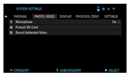
To change a particular value, follow the next few steps. Select the subcategory you need with the Scroll Wheel or Keypad buttons
Press the OK button to select a particular value (once selected it will turn red).

Change the value with the Scroll Wheel or Keypad buttons

To select a new value, press OK button to confirm the change.
FUNCTIONS
PHOTO MODE
From the Homescreen: press the LEFT button to TAKE A PHOTO.
NOTE
You must have a micro SD card inserted in the device for these features to work and all files will be stored on the microSD card.
 PHOTOS
Allows you to take one photo at a time. The photo preview appears after a photograph is taken on the botton of the screen for several second.

VIDEO RECORDING
NOTE
You must have a micro SD card inserted in the device for these features to work.

All files will be stored on the microSD card. Recorded videos can be found in the Gallery of the device. The scope allows you to record videos in two modes.
 NORMAL
The default mode. While recording the Counter widget appears. In order to Start recording video.While on the Homescreen, Press the RIGHT button to activate video recording. Press the RIGHT button once more to Stop recording video.

RECOIL ACTIVATED VIDEO (RAV)
When you set your video record to RAV mode (from Shortcut Menu), the system buffers everything your scope sees. While you are in this
mode, the RAV widget appears and then after starting record the Time Counter appears.

After activating the RAV function in the Shortcut Carousel, return to the Homescreen. Continue the activation process by pressing the RIGHT button to activate the Video. Also, make sure you see
the RAV icon on the Homescreens upper left corner. Press the RIGHT button again to stop Video recording.

When a shot is fired, your scope experiences recoil (some airguns may not provide enough recoil
for RAV to be activated). The scope will record video prior to the shot be- ing taken, the moment of,
and some time after. Exact
settings may be adjusted
in the System Settings.
RECOIL ACTIVATED VIDEO
Recoil Activated Video (patent pending), offers a unique approach to taking videos with your Smart Sight. RAV offers you the ability to take a video before, during and after your shot has been fired. Perfect for those hunting moments when hitting your target, far outweighs the importance of remembering to turn on your video record. Simply set your RAV to ON, set your parameters and anytime you pull the trigger (RAV is activated from the recoil of your weapon), the sight will record a number of seconds before your shot and a number of seconds after. All conve- niently organized as one continuous video. Press the RIGHT button to Activate RAV from the Homescreen to Start. Video recording. Press the RIGHT button again to stop Video recording.
NOTE
It may be best to turn OFF the Microphone in conditions of extreme wind.
You can turn on the microphone and switch the quality of the video in the System Settings (Photo/
Video tab). To enter the System Settings:
- Open Shortcut Carousel by pressing the OK button and select the wrench icon with RIGHT or LEFT buttons
- Push OK button to enter the menu.
- Using the Scroll Wheel or Keypad buttons select Microphone. Press the OK button to select it.
- Change the setting with the Scroll Wheel or Keypad buttons and press the OK button to confirm the change. All files will be stored on the microSD card. Recorded videos can be found in the Gallery of thedevice.
RAV CALIBRATION
RAV (Recoil Activated Video) is a fantastic feature that allows you to set your scope to record your video when you fire your weapon. But as there are many types of calibers and platforms our standard RAV sensitivity may not be enough. IE small calibers that have little recoil, which fails to activate RAV. With this option you are able to adjust the sensitivity of your scope in order for it to recognize the light recoil and activate RAV.
NOTE
For best results you should only Calibrate RAV at a shooting range. ATN endorses safe and responsible recreational shooting, and does not recommend RAV calibration at home regardless of state law.
Open the Shortcut Carousel and navigate to Settings. Scroll to Profile/Zero and then select RAV cali- bration. You should see a
velocity rating in the upper
left corner ( _ . _ ft/s or m/s ) followed by “1, 2, 3”. The First circle is blinking denoting actively searching for input. While having
the RAV calibration active fire a round down range.


You should see example (9.4 ft/s) or something similar, as it will depend on the caliber and your platform. Once you get the first number press the center OK button to save. Repeat this process with only your desired input until there is a check mark on all numbers. If an error has been encountered either
with ammunition, loading, or any other possible malfunction, simply press the left button to leave RAV
calibration. Afterwards, please repeat the process. Once this has been accomplished your scopes RAV is calibrated to your caliber, grain, velocity, and platforms felt recoil.
By following this pro- cess, you should be able to use RAV with the ammunition and platform used during the calibration process..
NOTE
We have conducted tests to 22 Air rifle and 22 Long Rifle successfully increasing the sensitivity of RAV.
ZEROING
NOTE
Before zeroing your scope, please make sure the correct lens type is
selected. You can check this by going to the System Settings and selecting Settings. You will see
the subcategory Device Type. Please make sure you select the lens type of your scope.

This lets the system know which Scope you are actually using (ex- ample: Mars 4 19 mm or Mars 4 50 mm).
To Zero in your scope you will need to go to the Profile/ Zero section of the System Settings, or select it from the Shortcut Carousel.

To enter the System Settings, open Shortcut Carousel with OK button and select the wrench icon with RIGHT or LEFT buttons . Or select the Zero Reticle shortcut from the
Shortcut Carousel. Push the OK button to enter the menu.
Before you begin the Zeroing process, you will need to either create a new Profile or utilize an existing one. We recommend that
a new profile be created to understand the process better. Under the Profiles/Zero Category you will find the subcategories; Cur- rent, Other, Import from SD card, and Export to SD card.select Other.

There you will see Profile 1 and Create New Profile. Select Profile 1 and edit it, or create a new one and make changes to it. Once you select a profile, press the OK button to load it. Once the profile is loaded, it becomes your current profile.

Profiles are primarily used in order to utilize your scope on various weapons. This way, when moving your scope from one gun to the next, you can simply select the Profile that you have already created for the particular gun you are using. Multiple profiles are also used to zero in the scope, on the same gun, but at different ranges. For example, one Profile may be called AR 50 yards and another AR 200 yards. Allowing you to create two separate profiles to better fine tune your shooting solutions for both shorter and longer range shooting. In order to change the profile name to what you want, open the ATN Obsidian app and connect your Phone/Tablet to your scope.
NOTE
You will need to obtain a target that thermal is able to see. ATN sells Thermal Targets, or you can use any of the following items: Cold or Hot water bottle, hand warmers, or foil based tape.
To zero your rifle with the ATN device, you should follow the next few steps. In the System Settings,
Select the Profiles/Zero Tab. The main Subcategories of the Profiles/Zero are; Current, Other, Import from SD card, and Export to SD card. Select Current, by pressing the OK button.

There you will see Zero Reticle. We suggest you fill out all the ballistic info to the best of your ability before proceeding to Zero. This will save you time when you want to use the Ballistic Calculator at a later time.
Proceed to Zero the Ret- icle. Press the OK button to select Zero Reticle. You will see on your screen
a cross hair reticle. While keeping the gun as steady as possible, fire a round. Use the key pad and scroll
wheel to move the Red cross hair to the point of impact. While keeping the White crosshair in the same place you where aiming. Once you have placed the Red crosshair on the POI, press the OK button . A dialogue box will appear with options. Select Save & Exit.
NOTE
Although you may not need more then one shot to Zero in your scope, we do recommend that you repeat the process several times to make sure that you truly are Zeroed in. As you gain experience in Zeroing in
your scope it should take you no time at all to Zero it.
NOTE
In order to fine tune your zero. Select Zero Reticle once more. Press the OK button and select Zoom. Zoom in all the way and fire the weapon. If your POI is not where you had aimed, move the Red reticle to the POI and Exit & Save. This will insure your POI is the same on optical and maximum magnification.
RANGEFINDER

Using the Smart Range Finder will allow you to estimate the distance to your target, as long as you have
reasonable knowledge of the size of your target.
NOTE
To have this feature enabled you must acti- vate Advance Mode settings.

NOTE
Once the distance is measured, the value will be automatically integrated into your Ballistic
Calculator.
RANGEFINDER
Select the Flag Icon from the Shortcut Carousel.
Pressing the OK button will take you to the Main Screen of the Rangefinder feature. To measure the distance, follow the next steps:
- Put the arrow-mark on the top of the target and press the OK button, wait for the scope to take the readings (it will take a number of readings so try to keep your weapon steady);


- Put the arrow-mark under the target and press the OK button
- If satisfied with the value that was generated, press the Function button to go back
to the Homescreen or repeat steps 1 and 2, if necessary.

NOTE
During the measurement process, you can zoom in and out using the Scroll Wheel.
If the Target Height is incorrect you can change it:
- press the RIGHT button to enter the Menu;
- choose one of the presets or input the height manually;
- accept the height with OK button and go back to the Main Screen.
DISTANCE ENTRY
Allows you to input or correct the distance manually. Choose the Distance Entry option to launch this function


Change distance value using the Scroll Wheel or Keypad buttons To accept the new distance, press the OK button
BALLISTIC CALCULATOR


The Mars 4 has a fully integrated Ballistics Calculator that enables your scope to seamlessly adjust its point of impact. The first step in utilizing this function requires you to enter all relevant information into the Profile that is being used.
NOTE
To have this feature enabled you must activate Advance Mode settings.
NOTE
If you do not know all or part of this info (example: Initial Velocity) we recommend that you contact he manufacturer of the ammunition and/or the weapon that you are using. Generally this info should be found on the
manufacturer’s website.
Once your profile has been setup, you are ready to acti- vate the Ballistic Calculator on your sight. Open the Shortcut Carousel and follow the instructions in this section.
You will need to use your key pad and Scroll Wheel or Keypad buttons, to find the Ballistic Calculator bullseye icon. If this
function is off (indicated by a diagonal line running through the icon), you will need to turn it on by pressing the OK button while
having the icon selected. You will see the diagonal line disappear and a Ballistic Calculator icon will appear in the top right corner of the screen. Profiles which are not in use, are situated in the Other section. You can use an existing profile or create up to 6 new user profiles.
To edit a Profile, select it (highlighted in red) and press the OK button . Choose the action you want to perform; Load, Copy (Duplicate) or Delete the selected profile.
ENVIRONMENT NOTE
To have this feature enabled you must acti- vate advance mode set- tings. There are a number of
Environmental elements that may be entered to in- crease the precision of your shots.
Wind:
Wind strengths and di- rection are by far the most important of the group, especially during medium
to heavy winds. We highly
recommend that if you plan to shoot at ranges over 300 yards. Take wind readings and enter the information into your sight. Both wind speed and wind direction
are needed if you plan to make accurate shots. You can enter the information through the Environment shortcut or your mobile device using the Obsidian App with a WiFi connection to your scope, whichever you find easier.


Humidity:
Humidity must also be entered through the Environment shortcut or by utiliz- ing the Obsidian App.
Barometer Pressure, Altitude and Temperature:
Pressure, Altitude and Temperature will be set automatically using your sight’s internal sensors.
Other Data Collected:
The angle of your scope, as in relation to your target, is also noted and the Ballistic Calculator takes the information into its calculations.
SMART MIL-DOT-RETICLE
program the variance between hash marks in Mils into this Smart Mil Dot Reti- cle. Also, this reticle is Dynamic and adjusts with magnification throughout the entire zoom range! Plus, you can also use the ATN Ballistic Calculator to give you instantaneous POI adjustments with a Teal dot, on the reticle, giving you exactly where to place your hold over. Happy Shooting.


There are two ways you
can use the ATN Smart Mil
Dot reticle. You can use it
as a standalone Mil Dot
reticle or you can have the
ATN Ballistic Calculator
assist you in its use.
In standalone form, the
reticle will allow end users
to have a verified distance
between hash marks at all
magnification levels.
Follow the next few steps
to setup the Smart Mil Dot reticle.
- Click OK center button
- Select System Settings.
- Navigate to Profile/Zero.
- Select Mil-Dot-reticle
value, use your scroll wheel
to set the desired value,
and click OK button - Scroll up to Current Profile and click OK
- Go to the Display Tab in
system Settings and select
the Mil-dot reticle. Return
to Homescreen. To use the ATN Smart Mil Dot Reticle with your Ballistic Calculator follow the setup process outlined in the Ballistic Calculator section, insuring that you have the correct profile load setup, Ballistic Calculator is turned ON, environmental settings are correct, having the advanced settings activated.
Once all of these items are setup properly and you have selected the Mil Dot reticle from the available reticles in the Display section of the settings. When you return to the Home Screen, you will see the AT
smart Mil Dot reticle with a Teal Dot indicating your new POI/POA instead of the reticle moving to the POI/POA.
NOTE
Depending on the Mars 4 you have the Smart Mil Dot hash mark variance will differ: 19 mm — 4.0-10, 25 mm — 4.0-10, 50 mm — 2.0-10, 75 mm — 1.0-10. You are advised not to turn the system type to another just to utilize a maller Mil Dot value. This will result in unsafe shooting as the reticles are sized to the field of iew, and will otherwise provide a wild shot. Sec- ondly, the system will crash due to elements of the screen overlapping (75 mm having 4x the hashes in the same distance).
HOW TO PERFORM A NUC
NUC’ing helps to improve the image quality when the image is degraded by various environmental factors. There are multiple NUC tables that span the full operating temperature range, and the camera automatically selects the optimum table based on its temperature. You can set the system to perform a NUC automatically at a predefined time interval. Or, you can turn the automatic NUC off and NUC the system manually, when required. Also, you can use the NUC shortcut from the Home Screen by pressing the Power button, provided that you activated this shortcut in the system settings.


Example: Change of temperature, continuous viewing of a particular warm object, and movement from one environment to another all may cause image degradation.
 To clean up the image you will need to select NUC from the Shortcut Carousel after you select to NUC the system. The scope willperform the required calibration improving the visual quality of the image.
PIXEL CORRECTION PROCEDURE
Pixel Correction Procedure is intended to correct “neutral” pixels that are visible in the FOV, but are not responding to the changing environment or scenery. They may be white or black and remain static and or nonresponsive.
- Enter the Shortcut Carousel by pressing the OK button
- Select System Settings.
- Select Thermal Category
- Select Pixel Correction Subcategory
- Select Manual Correction
- You should see a targeting reticle, use the key pad and Scroll Wheel to move the reticle over the neutral pixel. If it is hard to target the neutral pixel, press the OK button and select Zoom. Use the Scroll Wheel to zoom in and out, on to the neutral pixel in order to isolate it. Once you
have isolated the neutral pixel, press the OK button to escape from the zoom function. - . Once the reticle is positioned over the neutral pixel, press the OK button and select Save. This hould correct the pixel.
NOTE
If after you have done the procedure outlined above and the neutral
pixel has not been corrected. Try the process on a pixel directly adjacent
to the neutral pixel in order.
RETICLE STYLE ADJUSTMENT


You can manage reticle style in the System Settings (Display section). To enter the System Set- tings, open the Shortcut
Carousel by pressing the OK button and selecting the rench icon with RIGHT or LEFT buttons. Press the OK button to enter the menu. Choose Display in Tab Menu. Movement between the tabs is carried out using the LEFT and RIGHT buttons . Using the Scroll Wheel or Keypad buttons , select the Reticle Style subcate- gory. Press the OK button to select it. To change the Reticle Shape press the OK button. Select the preferred Reticle style that suits your preference. Use the scopes Key Pad arrows to switch between shapes. To accept the Reticle, press the OK button. You can change Reticle Color to whatever color suits your preference. Movement etween the colors is carried out using the LEFT and RIGHT buttons . Press the OK button to accept your color.
SYSTEM SETTINGS
THERMAL

CONTRAST — the difference in luminance and color that makes an object more istinguishable. You may adjust the settings to Low/Medium/High. THERMAL SENSITIVITY — Allows you to select how sensitive the Thermal Sensor is in picking up
thermal heat signatures.
METERING MODE — The Center mode tells the sensor to concentrate on the heat signature in the center of the field of view and ignoring the background. The Matrix mode tells the sensor to look at the heat signature in the entire field of view and the background to give you a better image of the entire scene.
POWER BUTTON NUC — Turning this option ON, will allow you to do a quick NUC by tapping the Power Button on your control pad.
COLOR PALETTES — The range of colors used for thermal imaging.
PIXEL CORRECTION — This feature is intended to correct “neutral” pixels that are visible in the FOV, but are not responding to the changing environment or scenery. They may be white or black and remain static and or non-responsive.
PHOTO/VIDEO
PHOTO MODE — includes Single (capture a single photo).
MICROPHONE — sound recording (ON/OFF).
FORMAT SD CARD — after you choose this subcategory you’ll see a pop-up window asking you about formatting.

RECOIL ACTIVATED VIDEO
- Record Before Shot — the time before pulling the trigger (5 – 30 sec).
- Record After Shot — the time after pulling the trigger (5 – 30 sec).
DISPLAY
SCREEN BRIGHTNESS. Gives you a 1 to 5 numerical selection, with 1 be- ing the dimmest and 5 the brightest. It is recommended that you use the bright- est setting during the day for optimal performance.
DISPLAY WIDGETS — allows you to disable several widgets (Minimal/Ex- tended).

SLEEP MODE
- Sleep Mode — allows you to switch the mode (ON/OFF).
- Hibernation Time — can
be 1 – 60 min. RETICLE STYLE - Shape — you can choose the shape of your Reticle.
- Color — you can choose the color of your Reticle.
PROFILES/ZERO

CURRENT
- Zero Reticle — allows to enter zeroing mode.
- Drag Function — the flight path and characteristics of bullets divided into types (G1 – G8, GL)
- Ballistic Coefficient — measure of bullet’s ability
to overcome air resistance in flight. - Bullet Weight — influences the kinetic energy of the bullet downrange.
- Muzzle Velocity — is the velocity of the projectile as
soon as it leaves the barrel. - Zero Range — is the range that a firearm is sighted at.
- Sight Height — is referring to the distance between the center of the optics and the center of the barrel.
OTHER
- Profile Name — list of existing profiles.
- Create New Profile — allows to create up to 6 profiles.
SETTINGS
UNITS — can be Metric or Standard system.
DATA AND TIME
- Clock Source — allows you to choose different types of source to improve
the accuracy (Manual, WiFi). - Date Format — can be YYYY-MM-DD, MM-DD-YYYY, DD-MM-YYYY.
- Time Format — form of stating the time (24-hour or 12-hour).
- Date — enter the date.
- Time — enter the time.
- Time Zone — allows
you to choose a geo- raphical region with
standard time.
WIFI AND BLUETOOTH
— WiFi values are not changeable. - Remote controller —
Allows for pairing of X-Trac remote.

- Remote Controller Orientation — Allows you to choose the orientation of the remote, changing the direction of the scroll wheel.
- Rangefinder — Allows for pairing of the LBRF.
- ABL — Allows for pairing of the ABL Rangefinder.
- ABL Mode — Allows you to change the mode in which the ABL will function. Standard or Fog mode.
- WiFi Info.
- BinoX LRF.
DEVICE TYPE — to make all features work correctly you need to choose the type of lens you have.
ZOOM — allows you to choose different types of zoom (Standard, Extended). Extended Zoom will give an electronic zoom of 10x your optical Zoom. Example: 3–14x in Extended mode becomes 3–30x. However, we would like to caution you that you will begin to see considerable pixelation at such a zoom.
RESTORE FACTORY SETTINGS — allows to reset all the settings to default.
FIRMWARE VERSION — allows you to see the firmware version currently running on your sight.
We recommend that you register your product on our home page (www. atneu.com) in order to make sure that you are getting emails when new firmware versions become available. We are constantly working on new features, functions, and improvements that we provide to you free of charge via firmware upgrades.
BIX TECHNOLOGY
ABL PAIRING
NOTE
Make sure you have the Advanced Settings turned on in the Shortcut Carousel before roceeding.
- Insert battery into ABL and turn unit on via power switch.
- Activate Bluetooth within the carousel menu in the scope.
- Enter the System Settings menu via carousel Wrench icon.
- Navigate to settings menu at far right.
- Select WiFi and Bluetooth option.


- Select ABL option in the
menu. - Select pair from the ABL
dropdown menu. - You’ll notice the Bluetooth icon, in the upper right of the display, you will now have a swirling circle around itThis indicates the scope is search- ing for available Bluetooth devices.
- Short press the small button on the ABL
with the Bluetooth symbol, quickly 2 times. - You’ll now see that the Bluetooth icon in the upper right of the display is enveloped
in a colored circle. White in day mode and
yellow in night mode. After the pairing has
completed, the ABL menu option will display “Paired”, to the right. - Exit the setting menu and proceed to the ROFILES/ZERO menu.
- Navigate down to theZeroing ABL menu option and select it. The ABL
reticle will now appear on screen. - Having previously removed the Allen screw that
covers the visible red laser,
you can now move the ABL
reticle to the correct area of
the display to align the reticle with the infrared rang- ing laser. The visible red la- ser is used as a visual ref- erence point for zeroing. Use the arrow keys on the
keypad to move the reticle
to the correct position. - Once the box area of
the ABL reticle is centered
around the red laser, press the OK button to confirm the reticle orrection. - Exit the menu and returnto he Homescreen/Mainreticle screen of the scope.
- To range a target, press and release the Function button. The ABL reticle will instantly appear on screen Place the box area of the ABL reticle on the desired target and hold it there until the ranging process times out. You’ll now see the range in the upper left of your extended widgets has
updated and indicates
the correct range to the
target you just ranged.
NOTE
If you don’t want to wait for the ranging function to time out and need a quick range measurement press the function button to initiate ranging and press it once again to save the range to target.
LASER BALLISTICS PAIRING
- To do this you’ll need to power up the scope and allow it to reach its base reticle screen (home screen).
- After reaching the home screen you’ll next press the OK button on the scopes keypad, which will bring up the carousel menu.
- Press the LEFT arrow button until you reach the feature icon area of the menu (you’ll notice the WiFi icon. WiFi will be written in text in the upper left of the display).
- Using the UP or DOWN arrow keys on the keypad you will scroll until the BLUETOOTH icon s displayed in the center of the screen.
- Press the OK button to un-slash the icon. This indicates the activation of BLUETOOTH.
- Use the UP or DOWN arrow keys to scroll to the BALLISTIC calcula tor icon and use the OK button to un-slash it. This will save time and steps later when the LBRF is connected to the cope and ready for use with the ballistic calculator program.
- Scroll to the SYSTEM SETTINGS icon in the carousel menu (indicated by a wrench in the center of the screen, and the text “SYSTEM SETTINGS” in the upper left of the display). Press the OK button to access the SYSTEM SETTINGS MENU.
- Use the LEFT arrow key to navigate to the SETTINGS section of the menu.
- Scroll down to the “WiFi and Bluetooth”. Select this option by hitting the OK button.
- A new menu will appear. Scroll down to “Rangefinder” and select this option using the OK utton.
- A new menu will appear containing the options “Pair” and “Unpair”. Select the option to pair. This will activate Bluetooth searching , which searches for available Bluetooth devices. You’ll notice that the Bluetooth icon in the upper right of the scope’s display has a swirling circle around it indicating the search for the rangefinder.
- Next you’ll need the rangefinder in hand to press the power button on it. Press the power button on the rangefinder twice. This will sync the two devices. You’ll then see “Paired” to the right of Rangefinder” in the menu. Now you can exit the menus and return to the home screen.
BINOX 4K/4T PAIRING
- If you would like to use your ATN BinoX 4K/4T to transmit the range data to your ATN Smart HD scope via Bluetooth, please follow the next few steps in order to accomplish this.
- Make sure you have activated the advanced settings in your BinoX 4K/4T.
- Open the shortcut Carousel → System Settings → Settings → WiFi & Bluetooth → Broadcast LRF.
- Select Broadcast LRF and switch it “ON”.
- Turn on your ATN Smart HD scope. Make sure you have activated the advanced settings in the shortcut Carousel.
- Open the shortcut Carousel → System Settings → Settings → WiFi & Bluetooth → BinoX 4K/4T LRF.
- Select BinoX LRF and switch it “ON”.
- Now take your ATN BinoX 4K/4T and Short Press the power button. You should see the Rangefinding reticule appear. Once the BinoX ranges the target, the range data will automatically be transfered to your ATN Smart HD scope. If you have the Ballistic Calculator turned on and the Ballistic profile has been setup, your POA will change based on the reading the ATN Smart HD scope receives from the ATN BinoX 4K/4T.
X-TRAC PAIRING
- Activate the Bluetooth function in your ATN Smart HD Scope.
- Enter the system setting from the menu.
- Select the Settings Category.
- Select the WiFi and Bluetooth subcategory.
- Select Remote Controller.
- Select Pair. You should see a half circle move around in the upper right side of the screen around the Bluetooth Icon.
- Press and hold the Home Button and Top Arrow Button closest to the Directional Roller for 2 seconds, this will pair the X-TRAC to your scope.
NOTE
If you need additional trouble shooting assistance or how to use the X-Trac please refer to the X-Trac manual available online.
WARNINGS AND CAUTIONS
- Always remember to turn off the device when it is not in use.
- Do not disassemble, drop, open, crush, bend, deform, puncture, shred, microwave, incinerate, paint or insert foreign objects: it will void your warranty.
- Keep the scope in the provided protective cover when not in use.
- Avoid contact with dust, steam, and gas.
- This product contains natural rubber latex which may cause allergic reac- tions.
- The scope is a precision electro-optical instrument and must be handled
carefully. - Do not scratch the external lens surfaces or touch them with your fingers.
CAUTION
Failure to follow these safety instructions could result in damage to the
device!
MOBILE APPLICATIONS
Control your device and view a live streaming feed with our ATN Obsidian 4 app. After connecting your phone or tablet via WiFi to your ATN
device, you can see on your phone/ tablet screen what is shown in your optic’s viewfinder. Want to see what you’ve recorded so far? No problem open up the Gallery and playback your latest adventures. All your photos and videos are right at your fingertips.

In order to download the latest version of the ATN Obsidian 4 app. Please visit the iOS store or Google Play store. Search for “ATN Obsidian 4” install the application. To connect your ATN device to your smart phone or tablet, you must first enable WiFi on your ATN device via the shortcut carousel. Once enabled, you can access your WiFi settings on your phone or tablet and select the respective SSID (DeviceName_XXXX) to establish the connection. The default password is “atnsmarthd”. Once the connection has been successfully established, open your ATN Obsidian 4 app and your respective device should be shown on the home screen. Tap the button with your devices name to control your device, access live streaming as well as the gallery from your phone or tablet.
3 YEAR PRODUCT WARRANTY
This product is guaranteed to be free from manufacturing defects in material and workmanship under normal use for a period of 3 (three) years from the date of purchase. In the event a defect that is covered by the foregoing warranty occurs during the applicable period stated above, ATN Europe LTD, at its option, will either repair or replace the product, and such action on the part of ATN Europe LTD shall be the full extent of ATN Europe LTD’s liability, and the Customer’s sole and exclusive remedy. This warranty does not cover a product (a) used in other than its normal and customary manner; (b) subjected to misuse; (c) subjected to alterations, modifications or repairs by the Customer or by any party other than ATN Europe LTD without prior written consent of
ATN Europe LTD; (d) special order or “close-out” merchandise or merchandise sold “as-is” by either ATN Europe LTD or the ATN Europe LTD dealer; or (e) merchandise that has been discontinued by the manufacturer and either parts or replacement units are not available due to reasons beyond the control of ATN Europe LTD. ATN Europe LTD shall not be responsible for any defects or damage that in ATN Europe LTD’s opinion is a result from the mishandling, abuse, misuse, improper storage or improper operation, including use in conjunction with equipment which is electrically or mechanically incompatible with.
or of inferior quality to the product, as well as failure to maintain the environmental conditions specified by the manufacturer. This warranty is extended only to the original purchaser. Any breach of this warranty shall be waived unless the customer notifies ATN Europe LTD at the address noted below within the applicable warranty period. The customer understands and agrees that except for the foregoing warranty, no other warranties written or oral, statutory, expressed or implied, including any implied warranty of merchantability or fitness for a particular purpose, shall apply to the product. All such implied warranties are hereby and expressly disclaimed.
LIMITATION OF LIABILITY
ATN Europe LTD will not be liable for any claims, actions, suits, proceedings, costs, expenses, damages or liabilities arising out of the use of this product. Operation and use of the product are the sole responsibility of the Customer. ATN Europe LTD’s sole undertaking is limited to providing the products and services outlined herein in accordance with the terms and conditions of this Agreement. The provision of products sold and services performed by ATN Europe LTD to the Customer shall not be interpreted, construed, or regarded, either expressly or implied, as being for the benefit of or creating any obligation toward any third party of legal entity outside ATN Europe LTD and the Customer; ATN Europe LTD’s obligations under this Agreement extend solely to the Customer. ATN Europe LTD’s liability hereunder for damages, regardless of the form or action, shall not exceed the fees or other charges paid to ATN Europe LTD by the customer or customer’s dealer. ATN Europe LTD shall not, in any event, be liable for special, indirect, incidental, or onsequential damages, including, but not limited to, lost income, lost revenue, or lost profit, whether such damages were foreseeable or not at the time of purchase, and whether or not such damages arise out of a breach of warranty, a breach of agreement, negligence, strict liability or any other theory of liability.
PRODUCT WARRANTY REGISTRATION
In order to validate the warranty on your product, ATN Europe LTD must receive a completed Product Warranty Registration Card for each unit or complete warranty registration on our website at www.atneu.com. Please complete the included form and immediately mail it to our Service Center: ATN Europe LTD, Bulevard Tsarigradsko shosse 7-11 km. Parking lot of METRO 1 store, Sofia Bulgaria 1784.
OBTAINING WARRANTY SERVICE
To obtain warranty service on your unit, End-user must notify ATN Europe LTD service department by calling +359 884974545 or via e-mail support@ atneu.com to receive a Return Merchandise Authorization number (RMA). Merchandise Authorization number (RMA).
When returning please take or send the product, postage paid, with a copy of your sales receipt to our service center, ATN Europe LTD at the address noted above. All merchandise must be fully insured with the correct postage; ATN Europe LTD will not be responsible for improper postage or, missing or damaged merchandise during shipment.
When sending product back, please clearly mark the RMA# on the outside of the shipping box. Please include a letter that indicates your RMA#, Name, Return Address, reason for service return, Contact information such as valid telephone numbers and/or e-mail address and proof of purchases that will help us to establish the valid start date of the warranty. Product merchandise returns that do not have an RMA listed may be refused or a significant delay in processing may occur. Estimated Warranty service time is 10-20 business days. End-user/customer is responsible for postage to ATN Europe LTD for warranty service. ATN Europe LTD will cover return postage/shipping to European Union countries end-users/customers after warranty repair only if product is covered by aforementioned warranty. ATN Europe LTD will return product after warranty service by domestic TNT ground and/or domestic mail. Any other requested, required or international shipping method the postage/shipping fee will be the responsibility of the end-user/customer.