Product mentioned:
PRESENTATION
Aimpoint® red dot sights are designed for the ”two eyes open” method which greatly enhances situational awareness and target acquisition. Thanks to the optical design the red dot follows the movement of the user’s eye while remaining fixed on target, eliminating any need for centering.
Technical specification
| Optical system | |
| Magnification | 1X |
| Eye relief | Unlimited |
| Clear aperture | 18 mm / 0.7 in |
| NVD (2) compatible | Yes |
| Optical coating | Anti-reflex (AR) coating |
| Adjustments | 1 click ≈ 10 mm at 100 m / 0.4 in at 100 yds |
| Adjustment range (windage and elevation) | ±1 m at 100 m ±1 yds at 100 yds |
| Dot size | 2 MOA (1) |
| Dot intensity settings | 4 NVD, 6 daylight |
| Signature | No forward optical signature from the dot beyond 10 meters |
| Power source | |
| Battery type | One AAA size 1.5 V Alkaline LR03 or Lithium FR03 |
| Battery life (3) | More than 5 years of use at setting 7, more than 1 year at setting 8 and more than 10 years at NVD-setting (1-4). |
| Materials | |
| Sight and mount | High strength aluminum, hard anodized, black to dark gray, non-glare finish |
| Lens cover | Thermoplastic elastomer, black, non-glare finish |
| Size (L x W x H) | |
| Sight only | 83 mm × 40 mm × 49 mm 3.3 in × 1.6 in × 1.9 in |
| Sight with LRP mount | 85 x 52 x 61 mm 3.3 x 2.0 x 2.4 in |
| Weight | |
| Sight only (including battery) | 191 g (6.7 oz) |
| Sight with LRP mount (including lens covers and battery) | 243 g (8.6 oz) |
| Sight with spacer and LRP mount (including lens covers and battery) | 261 g (9.2 oz) |
| Height of optical axls | |
| Sight with LRP mount | 30 mm (1.2 in) |
| Sight with spacer and LRP mount | 39 mm (1.5 in) |
| Environmental specification | |
| Temperature range (operation) | -45 °C to +71 °C -49 °F to +160 °F |
| Temperature range (storage) | 51 °C to +71 °C -60 °F to +160 °F |
| Water resistance | 45 m / 147 ft. (operable) |
| Chemical resistance | Withstands occasional contamination by weapons cleaners, lubricants, oil or insect repellants |
1 MOA: Minute Of Angle, 1 MOA ≈ 30 mm at 100 m or ≈ 1” at 100 yds
2 NVD: Night Vision Device
3 Battery life: Values valid at room temperature for a quality battery
Overview (configuration)

- Drill tool
- Drill tool guide
- Custom turret ring
- Custom turret
- A turret
- B turret
- C turret
- D turret
- Rear flip-up lens cover (configuration)
- Elevation adjustment screw
- Locking tab
- Front flip-up lens cover (configuration)
- Battery compartment
- AAA-size battery LR6 / FR6
- Battery cap
- Screw (for LRP mount only)
- Screw (for spacer and LRP mount)
- Micro LRP mount (configuration)
- Spacer (configuration)
- Windage adjustment screw
- Wind correction turret
- Intensity switch
- Spring lock
- Aimpoint tool (Torx T10)
OPERATION
WARNING: Ensure the weapon is not loaded and thesafety selector is in the ”safe” position before attempting to install, remove or perform maintenance.
Install battery
Remove the front flip-up lens cover by pushing on the hinge in the direction away from the sight.
Loosen and remove the battery cap.
Insert battery with the positive end (+) toward the sight and the negative end (-) toward the battery cap as shown in Fig. 1.
CAUTION: Check that the o-ring is in good condition and in position to ensure there is no water leakage into the battery compartment.
Tighten the battery cap. As resistance is encountered, continue tightening until the battery cap will no longer turn.
Verify that the red dot is visible.
Re-install the front flip-up lens cover to the sight.
NOTE: For long term storage of the sight, remove the battery.
Install the sight
Depending on choice of configuration the sight is delivered with or without the Micro LRP mount and the spacer. The configuration with the Micro LRP mount and the configuration with the Micro LRP mount and spacer are assembled at delivery. The configurations also includes the front and rear flip-up lens covers.
For installation of another mount onto the sight see “4 Mount installation”.
For installation on a weapon, follow the instructions in the accompanying user manual for the mount.
Ballistic turrets
CompM5b™ is fitted with interchangeable ballistic turrets for quick elevation adjustments calculated for projectile drop. Current setting is shown next to the locking tab.
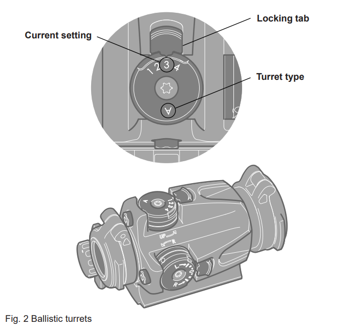
Table 1 Elevation adjustments
| Turret | Setting | Elevation adjustment (angle) – MOA | Elevation adjustment (angle) – MIL |
| A: 1 (zeroing setting) | 0 | 0 | |
| A. 2 | 2.4 | 0.72 | |
| A: 3 | 5.3 | 1.58 | |
| A: 4 | 8.8 | 2.61 | |
| B: 1 (zeroing setting) | 0 | 0 | |
| B: 2 | 2.9 | 0.86 | |
| B: 3 | 6.4 | 1.89 | |
| B: 4 | 10.6 | 3.15 | |
| B: 5 | 15.9 | 4.71 | |
| C: 1 (zeroing setting) | 0 | 0 | |
| C: 2 | 2.8 | 0.84 | |
| C: 3 | 6.0 | 1.79 | |
| C: 4 | 9.8 | 2.89 | |
| D: 1 (zeroing setting) | 0 | 0 | |
| D: 2 | 3.2 | 0.95 | |
| D: 3 | 6.9 | 2.05 | |
| D: 4 | 11.2 | 3.32 | |
| D: 5 | 16.2 | 4.8 | |
| D: 6 | 22.1 | 6.55 | |
| D: 7 | 29.1 | 8.63 |
Remove / install ballistic turrets
To remove / install a ballistic turret:
- Set the installed turret to setting ”1” (”A” Fig. 3).
- Push the locking tab in the direction away from the turret to disengage the turret.
- While the locking tab is disengaged, remove / install turret.
NOTE: Only remove / install ballistic turrets when the locking tab is pointing to setting “1” on the ballistic turret (”A” Fig. 3).
CAUTION: ALWAYS perform zeroing if the turret has been changed or replaced.
CAUTION: NEVER use the sight without ballistic or wind turret installed.
CAUTION: DO NOT turn the exposed mechanism when the turret has been removed! (“B” Fig. 3). See “5.3 Realign the ballistic turret” on how to to realign the ballistic turret.

Zeroing
CAUTION: ALWAYS perform zeroing if the ballistic turret has been changed or replaced.
CAUTION: ALWAYS perform zeroing with the ballistic turret set to the “1” setting and the wind correction turret set to the “0” setting.
CAUTION: DO NOT continue to adjust windage and elevation screws if you encounter resistance.
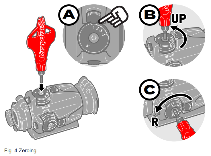
Zeroing is performed by adjusting the torx T10 adjustment screw positioned in the center of the ballistic turret and the wind correction turret. See Fig. 4.
To perform zeroing:
- Open lens covers and adjust the intensity to a comfortable setting for the red dot to contrast against the target.
- Set the ballistic turret to the ”1” setting (see ”A” in Fig. 4).
- Set the wind correction turret to the ”0” setting.
- Fire at least three shots at the zeroing target and evaluate Points Of Impact (POI).
- Elevation adjustments (see ”B” in Fig. 4):
- Turn elevation adjustment screw counterclockwise to move POI up (UP).
- turn elevation adjustment screw clockwise to move POI down.
- Windage adjustments (see ”C” in Fig. 4):
- Turn windage adjustment screw counterclockwise to move POI to the right (R).
- Turn windage screw clockwise to move POI to the left.
NOTE: Each click of the adjustment screws corresponds to 10 mm movement of POI at 100 m (20 mm at 200 m).
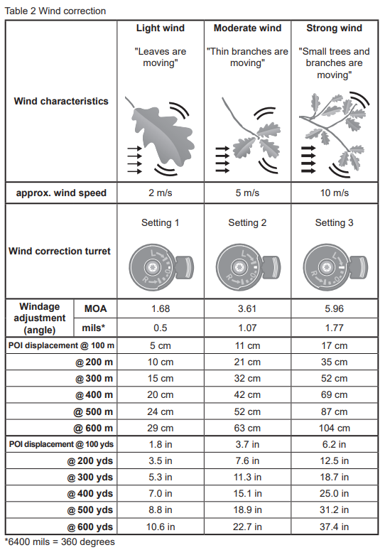
Wind correction
CompM5b™ is fitted with a wind correction turret for quick windage adjustments to compensate for drift of the projectile in light, moderate or strong crosswinds.
- To account for crosswind from your left hand side, turn the turret in the L-direction (clockwise) to move Point Of Impact (POI) to the left.
- To account for crosswind from your right hand side, turn the turret in the R-direction (counterclockwise) to move POI to the right.

Custom turret and custom turret ring
The custom turret allows an operator to customize the sight by creating elevation settings to adapt to any ballistic profile.
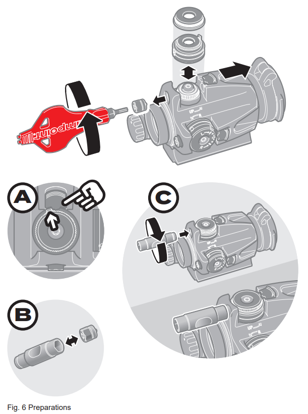
Preparations
- Put the custom turret ring on the custom turret.
- Install the assembled custom turret and custom turret ring on the sight by following instructions in 2.4.
- Perform zeroing in accordance with instructions in 2.5. When zeroing, ensure that the custom turret and custom turret ring is set to its starting position (”A” / Fig. 6).
- Loosen and remove the spring lock with the T10 Aimpoint tool. Alternatively, use the hex key socket on the drill tool guide to loosen the spring lock (”B” / Fig. 6)
- Install the drill guide to the sight as shown in “C” / Fig. 6. The drill tool guide ensures that the drill does not damage the turret when creating a mark.
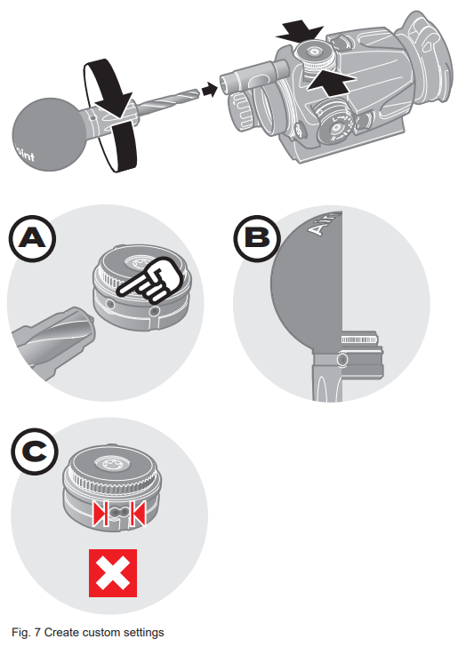
Create a custom elevation setting
Set the custom turret and custom turret ring to a desired setting.
NOTE: The serrations on the custom turret ring fits the indicator on the locking tab to produce “clicks”. Each custom turret ring clicks corresponds to a 20 mm movement of Point of Impact (POI) at 100 m. Turning the turret counterclockwise results in moving POI up. Similarly, turning the turret clockwise moves POI down.
Insert the drill tool into the drill tool guide as shown in Fig. 7.
CAUTION: DO NOT USE the drill tool without the drill tool guide. Using the drill tool without the guide can cause irreversible damage to the custom turret and the sight.
Firmly hold the custom turret while turning the drill tool to create a mark (”A” / Fig. 7).
Remove the drill tool and inspect the mark. The mark shall be similar to the reference mark on the drill tool (”B” / Fig. 7).
Repeat the steps c to d to create more marks in the custom turret.
CAUTION: DO NOT create overlapping marks (“C” / Fig 7). Ensure the custom turret is turned at least 3 clicks between each setting.
Remove the drill tool and the drill tool guide.
Remove the custom turret ring. Do not remove the custom turret.
Reinstall the spring lock to the sight and tighten with the T10 Aimpoint tool or alternatively use the hex key socket on the drill tool guide (“B” / Fig. 6).
NOTE: The custom turret ring offers 60 clicks of adjustment from the chosen Zero Range. At very long distances from the Zero Range, the amount of adjustment needed to accurately hit a target may become to large. Choose a greater Zero Range in order to extend the effective range up to the desired distance.
EXTREME CONDITIONS
- Extreme heat (humid or dry): No special procedures required.
- Extreme cold. No special procedures required.
- Salt air. No special procedures required:
- Sea spray, water, mud and snow: Ensure that the battery cap is tightened before exposing the sight to sea spray, mud and snow. Keep the lens covers closed when the sight is not being used. Clean the lenses with a lens soft cloth and wipe the sight dry as soon as possible after exposure to water, sea spray, mud or snow. Before and/or after severe exposure to sea water it is recommended to apply a light coat of thin rust-preventing oil to items 10, 11, 20, and 23 (Fig. 1) and lightly wipe with a dry
- soft cloth.
- Dust storms and sand storms: Keep lens covers closed when sight is not being used.
- High altitudes: No special procedures required.
CAUTION: The lenses should never be cleaned with fingers – always use a soft lens cloth. If no lens paper/cloth available:
- To clear away debris (sand, grass etc): blow away the dirt or rinse with clear water
- To clean lenses: fog the lenses or rinse with clear water and clean them with a soft piece of cloth.
MOUNT INSTALLATION
To avoid damage to the sight and for proper assembly of a mount onto the sight, the original screws must be tightened by hand and with the tool.
- Place the sight upside down in your hand.
- Press the mount against the sight and verify there is no gap.
- Apply thread locking fluid to the threads and install the screws.
- Tighten the screws in a crosswise pattern with the Aimpoint tool (Torx T10). Tighten until a resistance is encountered. Proceed with another 1/4 to 1/2 turn until fully tightened (1.35 Nm / 1.0 ft·lb).
CAUTION: Do not overtighten.
TROUBLESHOOTING
The red dot does not appear or has disappeared
Clean contact surfaces in the battery compartment and verify that the battery is working and that it is installed correctly. Verify that the battery cap is fully tightened. If the intensity switch is defective, notify local dealer/armourer.
The sight is impossible to zero
If an adjustment screw is at its limit, check the alignment of mount and barrel. If the issue remains perform a factory reset, see “5.4 Factory reset”.
If point of impact is moving, check the stability of mount.
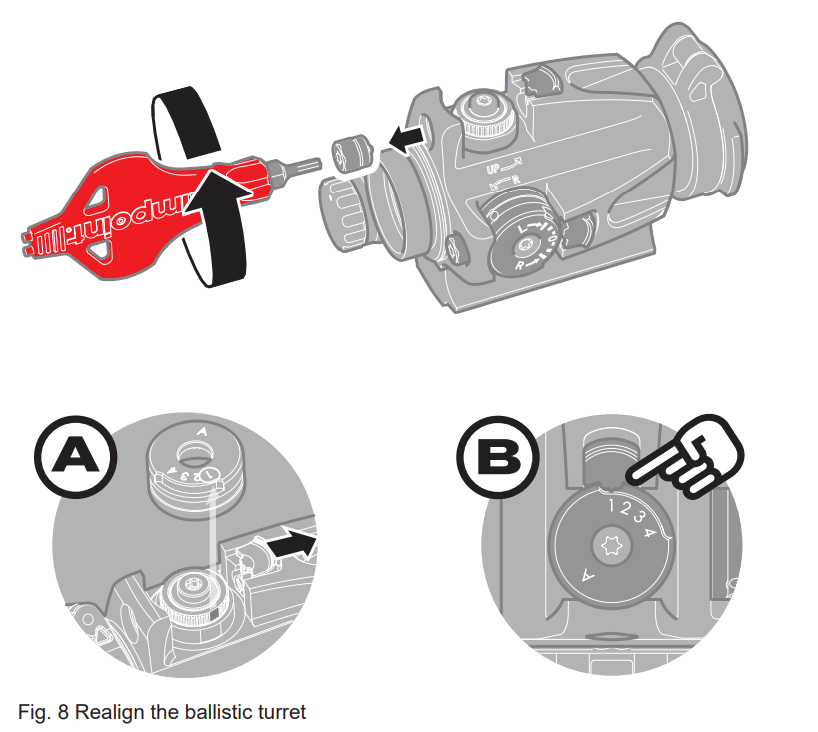
Realign the ballistic turret
If the exposed mechanism has been turn when the turret has been removed (“B” Fig. 3) it might be impossible to install the turret again. The exposed mechanism and the turret must be align again.
- Remove the spring lock.
- Disengage the locking tab (”A” / Fig. 8).
- Install the turret (”A” / Fig. 8). There is a groove in the mechanism that match the starting position (“1”) in the turret.
- Keep the locking tab disengaged and turn the turret clockwise until it comes to a stop.
CAUTION: Do not attempt to turn the turret further by force.
- Turn the turret counter clockwise to the starting position (“1”) (”B” / Fig. 8).
- Engage the locking tab.
- Reinstall the spring lock.
Factory reset
- Remove the spring lock.
- Disengage the locking tab.
- Turn the turret clockwise until it comes to a stop.
CAUTION: Do not attempt to turn the turret further by force.
- Turn the turret counter clockwise to the starting position (“1”).
- Reinstall the spring lock.