Product:
Electromagnetic compatibility. This product complies with the requirements of European standard EN 55032: 2015, Class A.
Caution: Operating this product in a residential area may cause radio interference.
Attention! A license is required for Thermal Imaging Front Attachment Proton FXQ30 when exporting outside your country.
This product is subject to change in line with improvements to its design.
The current version of the User’s Manual can be found on the website www.pulsar-vision.com
Package Contents
- Proton FXQ30
- Carrying Case
- 2x APS 5 Rechargeable Battery
- 2x Lock-cover for APS 5 Battery
- Battery Pack Charger
- Power Adapter
- USB Type-C Cable
- Quick Start Guide
- Lens-Cleaning Cloth
- Warranty Card
Description
Thermal Imaging Front Attachment PROTON XQ30 is a multipurpose device that allows you to quickly and easily transform a daylight optical sight into a thermal imaging one. The attachment is mounted on the lens of an optical sight with the help of adapters designed for various lens diameters. The attachment does not require any additional adjustment. The attachment is intended for various applications, including hunting, sport shooting, night photography & video recording, and surveillance.
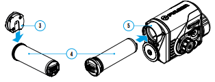
Components and controls
1. Lens cover
2. Eyepiece cover
3. Lock-cover for APS 5 Battery
4. Battery pack
5. Battery compartment
6. ON button
7. REC button
8. Controller
9. USB port
10. Objective lens end of daylight optical sight
11. Insert
12. Adapter
13. Screws
14. Tightening screw
15. Screw
16. Adapter lever
17. Mount

Description of buttons function
| BUTTON | SHORT PRESS | LONG PRESS | ROTATION |
| ON / OFF button (6) | Turn on device / Turn on display / Device calibration | Turn off device / Turn off display | – |
| REC button (7) | Start/Pause/Resume video recording / Photography | Toggle between photo/video mode Stop video recording |
– |
| Controller (8) | Enter quick menu / Switch between quick menu items / Confirm selection |
Exit quick menu / Enter/exit main menu | Parameter change / Main menu navigation |
Charging battery pack
The PROTON FXQ30 thermal imaging attachment comes with an APS 5 rechargeable Lithium-ion battery. APS 5 batteries support USB Power Delivery fast charging technology when using a standard charging set (charger, USB Type-C cable, power adapter). Before first use, make sure the battery is fully charged.
Option 1
- Install the APS 5 battery (4) in the battery compartment (5) of the device.
- Connect the USB cable (21) to the USB Type-C connector (9) of the device.
- Connect the other end of the USB cable (21) to the Power Adapter (22).
- Plug the Power Adapter (22) into a 100-240 V socket (23).
Option 2
- Insert the APS 5 battery (4) along the guide into the APS 5 charger (18) slot as far as it will go (see Fig.). The APS charger is supplied with your device and sold separately.
- Connect the plug of the USB Type-C cable (21) to the USB Type-C connector of the Power Adapter (20).
- Plug the Power Adapter (22) into a 100-240 V socket (23).
- Connect the other end of the USB Type-C cable (21) to the USB Type-C connector (20) of the charger.
- LED indicators (19) will display the battery charge level (see Table).
Note: Two batteries can be charged at the same time, a second slot is provided for it.


![]()

| LED INDICATION (19) IN THE BATTERY CHARGING MODE | |
| Battery charge level is from 0% to 25% | |
| Battery charge level is from 26% to 50% | |
| Battery charge level is from 51% to 80% | |
| Battery charge level is from 81% to 99% | |
| Battery is fully charged. It can be disconnected from the charger. | |
| Defective battery. Do not use the battery! |
|
| LED INDICATION (19) IN THE STANDBY MODE* | |
| Battery charge level is from 0% to 25% | |
| Battery charge level is from 26% to 50% | |
| Battery charge level is from 51% to 80% | |
| Battery charge level is from 81% to 99% | |
| Battery is fully charged. It can be disconnected from the charger. | |
| Defective battery. Do not use the battery! |
|
* Standby mode is when the batteries are in the charger but the Power Adapter is not connected. In this mode, the indicators are only on for 10 seconds.
Attention! When using a Power Adapter that does not support USB Power Delivery fast charging technology, the flicker frequency of the LED indicators decreases by a factor of 3 and the charge time increases.
Attention! The charger heats up during fast charging. Excess heat is removed through the radiator and does not affect the device operation.
Installing Battery Pack
- Put the Lock-cover (3) on the rechargeable APS 5 battery (4).
- Insert the APS 5 battery (4) along the guide into the battery compartment (5).
- Lock the battery (4) by turning the Lock-cover (3) clockwise until it stops.
- Turn the Lock-cover (3) counter-clockwise to remove the battery (4).
Operation
Mounting attachment on optical sight
- Remove the eyepiece cover (2).
- Select the Ring Adapter (12) (sold separately) with the insert (11) of the required diameter depending on the outer diameter of the lens of your optical sight (10) (see Table). The designation 42 mm / 50 mm / 56 mm in the name of the adapter means the lens diameter of the optical sight
Selection table for optical sight inserts
| Ring Adapter model | The internal diameter of the insert needs to match the outer diameter of the objective lens housing of the daylight optical device it is being installed on | |
| Insert internal diameter, mm | Suitable for lens housing of daylight optical devices with an outer diameter of, mm | |
| PSP Ring Adapter 42 mm | 45.5 | 45.5 |
| 46 | 46 | |
| 46.5 | 46.5 | |
| 47 | 46.7-47.6 | |
| 48 | 47.7- 48.6 | |
| 49 | 48.7-49.6 | |
| 50 | 49.7-50.6 | |
| PSP Ring Adapter 50 mm | 51.6 | 51.6 |
| 53.4 | 53.4 | |
| 55 | 54.7-55.6 | |
| 56 | 55.7-56.6 | |
| 57 | 56.7-57.6 | |
| 58 | 57.7-58.6 | |
| 58 | 58.7-59.6 | |
| PSP Ring Adapter 56 mm | 60 | 59.7-60.6 |
| 61 | 60.7-61.6 | |
| 62 | 61.7-62.6 | |
| 63 | 62.7-63.6 | |
| 64 | 63.7-64.6 | |
| 65 | 64.7-65.6 | |
- Screw together the Ring Adapter (12) and the attachment along the threads of the mounting area (17) until it stops. Then untighten a little (no more than one turn) so that the lever (16) is on the right side (see Figure).
- Evenly tighten the screws (13) until the ball joint grips in the Ring Adapter (12).
- Apply 2-3 strips of double-sided tape to the outer surface of the insert (11) of your choice.
- Push the insert (11) of your choice into the Ring Adapter (12) until it stops.
- Move the lever (16) to the OPEN position.
- Before installing the Ring Adapter (12) onto the optical sight, it is recommended to degrease the lens body of the optical sight (10).
- Mount the Ring Adapter (12) with the insert (11) onto the lens of the daylight optical sight (10) as far as it will go.
- If the Ring Adaptor (12) with the insert (11) selected according to the table cannot be mounted onto the lens (10), follow the steps below:
– Loosen the locking screw (14) with a 2mm Allen key.
– Untighten the screw (15) with a hex wrench (S = 4mm) until the Ring
Adaptor with the insert can be mounted onto the lens (10). - Move the lever (16) from its initial OPEN position to the CLOSE position.
- Loosen the locking screw (14) with a 2mm Allen key, if it hasn’t been done before.
- ighten the screw (15) using a 4mm Allen key. The clamping force should be 1.5-2 Nm (use a torque screwdriver) to ensure the lever is correctly tightened (16), while the Ring Adapter with the attachment should not move relative to the body of the optical sight (10). If necessary, tighten or loosen the screw (15) to operate the lever (16) in the best way possible.
- Tighten the locking screw (14) as far as it will go.
- Turn on the attachment by briefly pressing the ON button (6).
- Align the display center with the crosshairs of the reticle by tilting the attachment.
- Align top and bottom display boundaries parallel to the horizontal axis of the optical sight by turning the attachment clockwise or counterclockwise.
- Having reached the best possible position of the attachment, tighten the two screws (13) until stop. The clamping force should be 6.5-7.5 N·m (use a torque screwdriver to check).

Powering on and image setup
- Remove the lens cover (1).
- Press the ON button (6) to turn on the attachment.
If necessary, adjust the reticle sharpness according to the instructions for your scope. - Enter the main menu with a long press of the controller button (8) and select the desired calibration mode: manual (M), semi-automatic (SA) or automatic (A).
- Calibrate the image by briefly pressing the ON button (6). Close the lens cover before manual calibration.
- Select the desired observation mode (Forest, Rocks, Identification or User) in the main menu. User mode allows you to change and save user brightness and contrast settings in the quick menu.
- Enter the main menu with a long press of the controller (8) button and select the desired color palette (see the Main Menu Functions section of the full version manual for details).
- Activate the quick menu by briefly pressing the controller button (8) to adjust the brightness and contrast of the display (see the Quick Menu Functions section of the full version manual for details).
- Upon completion of use turn the device off by a long press of the ON button (6)
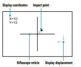
Display Calibration
The attachment is configured so that after fitting onto an optical sight that had been properly zeroed, no adjustment of the aiming point is required. Yet if point of impact change is observed after putting on the attachment, you can fix it with display calibration procedure.
- To enter display calibration mode, first press and hold the controller (8) button for 10 seconds.
- The display coordinates X=0; Y=0 will appear.
- Rotate the controller ring (8) to move the display horizontally (X axis) and vertically (Y axis) so that the point of impact moves to the centre of the riflescope reticle.
- Press the controller (8) button to toggle between the X and Y coordinates.
- The image offset range is +/- 20 pixels horizontally (X axis), +/- 20 pixels vertically (Y axis).
- To exit the menu and save the settings, press and hold the controller (8) button for two seconds.
Stream Vision App
Download the Stream Vision app to stream the image (via Wi-Fi) from your device to a smartphone or tablet, to view recorded files and update the software on the device. A detailed user guide is available at pulsar-vision.com

Specifications
| MODEL | PROTON FXQ30 |
| SKU | 76653 |
| MICROBOLOMETER | |
| Type | Uncooled |
| Resolution, Pixels | 384×288 |
| Pixel Pitch, µm | 17 |
| Frame Reate, Hz | 50 |
| OPTICAL CHARACTERISTICS | |
| Magnification of attachment, x | 1 |
| Recommended daylight optics magnification, x | 1.5-4 |
| Lens | F30/1.2 |
| Field-of-view (Horizontal), deg/m per 100 m | 12.4 / 21.8 |
| Detection Range (animal height 1.7 m), m/y | 900 / 984.3 |
| Minimum Observation Distance, m/y | 15/16.4 |
| DISPLAY | |
| Type | AMOLED |
| Resolution, Pixels | 1024×768 |
| OPERATIONAL CHARACTERISTICS | |
| Power Supply, V | 3-4.2 |
| Battery type/Capacity/Rated Output Voltage | Li-Ion Battery Pack APS 5 / 4900 mAh / DC 3.7 V |
| External Power Supply | 5 V (USB) |
| Max. Battery Pack Life (at t = 22 °C), Hour* | 6 |
| Maximum Recoil Power When Used with a Rifled Weapon, Joule | 6000 |
| Maximum Shock-Resistance When Used with a Slug Gun, Caliber | 12 |
| Degree of protection IP code (IEC60529) | IPX7 |
| Operating temperature, °C | -25 … +50 |
| Overall Dimensions, mm/inch | 119х58х75 / 4.69×2.28×2.95 |
| Weight (without battery), kg/oz | 0.3 / 10.59 |
| VIDEO RECORDER | |
| Photo/Video Resolution, Pixels | 864х648 |
| Video/Photo Format | .mp4/.jpg |
| Built-in Memory | 16 GB |
| WI-FI CHANNEL | |
| Frequency | 2.4 GHz |
| Standard | 802.11 b/g |
| Line-of-Sight Reception Range, m/y** | up to 15 / 16.4 |
* Actual operating time will depend to what extent the Wi-Fi and built-in video recorder is used.
**Reception range may vary depending on various factors: the presence of obstacles, other Wi-Fi networks.
The device repair is possible within five years.


Is goed te volgen had dit nodig om deze goed te kunnen inschieten . Dank U