Product:
https://www.optics-trade.eu/en/pulsar-forward-f455-digital-night-vision-attachment.html
This text is a transcription of the file in PDF format.
Specifications
| MODEL | FORWARD F455 |
| SKU# | 78186 |
| OPTICAL SPECIFICATIONS | |
| Lens focus, mm | 50 |
| Relative aperture, D/f | 1:1 |
| Field of view (horizontal), ° | 6.3 |
| Field of view (horizontal), m at 100m | 11 |
| Max. observation range of an animal 1.7 m high, m | 500 |
| Minimum focusing distance, m | 5 |
| Recommended magnification of the daytime sight | 2-8 |
| ELECTRONIC SPECIFICATIONS | |
| Sensor type / resolution | CMOS HD 1280X720 |
| Display type / resolution | AMOLED 1746×1000 |
| Sensitivity, mW (wavelength 780nm, 25 lines/mm resolution) | 1.5×10- ⁵ |
| Sensitivity, mW (wavelength 915nm, 25 lines/mm resolution) | 5.5×10- ⁵ |
| DETACHABLE IR ILLUMINATOR | |
| Type / wavelength, nm | LED 940 |
| OPERATING FEATURES | |
| Power supply, V | 3.0 – 4.2 |
| Battery type | Li-ion Battery Pack |
| Capacity | IPS7 (6400 mAh) |
| Rated Output Voltage | DC 3.7V |
| External power supply | Micro USB Type B (5V) |
| Battery life at temp. = 22 ° C (Wi-Fi off, IR off), hrs | 9 |
| Maximum recoil power on a rifled weapon, Joules | 6000 |
| Maximum recoil power on a smooth-bore weapon, calibre | 12 |
| Degree of protection, IP code (IEC60529) | IPX7 |
| Operating temperature, °C/F | -25 … +50 / -13 … +122 |
| Dimensions, mm/inch | 155х136х77 / 6.1×5.35×3.03 |
| Weight, kg/oz | 0.83 / 29.28 |
| VIDEO RECORDER | |
| Video/photo resolution, pixels | 1280×720 |
| Video / photo format | .mp4 / .jpg |
| Built-in memory | 16GB |
| WI-FI CHANNEL | |
| Frequency | 2.4 GHz |
| Standard | 802.11 b/g/n |
Improvements may be made to the design and software of this product to enhance its user features.
Package Contents
- Digital night vision attachment
- Carrying case
- Battery Pack
- Battery charger
- Mains adapter
- MicroUSB cable
- Quick start guide
- Lens cloth
- Warranty card
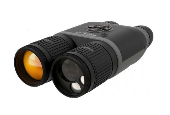
Description
The Forward F455 digital night vision attachment is a versatile attachment that allows you to quickly and easily transform a daytime optical sight into a night one. The attachment is mounted onto the lens of an optical sight with the aid of adapters designed for various lens diameters. The attachment does not require any additional ranging. The attachment is intended for various applications, including hunting, sport shooting, night photography and video recording, and observation.
Features
- 1280×720 HD sensor
- Enhanced night-time sensitivity
- Simple transformation of daytime optical sight into night sight
- Preserves the benefits of daytime optics in night-time conditions
- Aiming point stability
- Comfortable use in a wide range of daytime optical magnifications
- Invisible long-range IR Illuminator
- SumLight™ enhanced sensitivity software
- Detection distance of up to 500m
- Instant power up
- Built-in video
- Power from quick-release, high-capacity B-pack rechargeable batteries
- Four-point mounting system with automatic clamp
- Compatibility with other manufacturers’ adapters
- High calibre recoil resistance 12 gauge, 9.3×64, 0.375H&H
- Wi-Fi integration with iOS and Android devices
- Stream Vision: Remote control surveillance and live YouTube streaming via smartphone
- Remote software updates
- Fully waterproof (IPX7)
- Extreme operating temperature range (-25 … +50°С / -13F … +122 F)
- MicroUSB Power Bank charging
Units and controls
1. Lens cover
2. Eyepiece cover
3. Battery compartment cover
4. Battery locking lever
5. Rechargeable battery
6. RIGHT button
7. M (MENU) button
8. LEFT button
9. ON button
10. Lens focus knob
11. IR illuminator cover
12. IR illuminator connector plug
13. IR illuminator installation connector
14. MicroUSB port
15. Weaver rail
16. Adapter cover*
17. Optical sight lens
18. Insert*
19. Adapter*
20. Tightening screw
21. Screw
22. Adapter lever
23. Attachment point
24. IR button
25. IR illuminator lever

*Items of Cover Ring Adapter FN (available separately)
Description of Controls
| Button | Operating Mode | First brief press | Other brief presses |
Long press |
| ON (9) | Device off | Power on device | – | Power on device |
| Display off | Turn display on | – | Turn device off | |
| Device turned on, quick menu, main menu |
– | Display off / device powered off |
||
| LEFT (8) | Device turned on | Turn on SumLight™ |
Turn off SumLight™ |
Wi-Fi on / Wi-Fi off |
| Navigation through menu | Navigation upwards, downwards, counter-clockwise | |||
| Quick menu | Reduce value | |||
| MENU (7) |
Device turned on | Open quick menu | Open main menu | |
| Navigation through menu | Confirm selection | Exit submenu without confirming selection / exit menu (go to monitoring mode |
||
| Quick menu | Navigation upwards | Exit quick menu | ||
| RIGHT (6) |
Device powered on (Video mode) |
Start video recording |
– | Turn off video recording / Switch to Photo mode |
| Device powered on (Photo mode) |
Take a photo | Switch to Video mode | ||
| Navigation through menu | Downwards / rightwards / clockwise | |||
| Increase value | ||||
| IR (24) | Device turned on, quick menu, main menu |
IR illuminator on switch |
Adjust IR strength | IR illuminator off switch |
Operating Features
The Forward F455 attachment is designed for long-term use. Please follow these guidelines to ensure long life and maximum performance:
- Before using the attachment make sure you mount it according to the instructions in the “Mounting the attachment on an optical sight” section.
- Power off the attachment after use.
- Do not repair or dismantle a attachment under guarantee by yourself!
- The attachment can be used over a wide range of temperatures. If the attachment has been operated in the cold and brought into a warm room, do not remove it from its carrying case for at least 2-3 hours; this will prevent condensation forming on the external optical elements.
- Inspect and maintain the attachment regularly to ensure trouble-free operation and to avert and eliminate the cases of premature wear and tear and failure of components.
- The battery must not be exposed to excessive heat from the sun’s rays, fire of other heat sources.
Using the Battery Pack
The Forward F455 attachment is supplied with a rechargeable IPS7 Lithium-ion Battery Pack which allows the attachment to be used for up to 9 hours. Charge the battery before first use.
Charging the Battery Pack:
- Attach the microUSB plug of the USB cable to the microUSB connector (C) on the charger.
- Connect the USB plug on the cable to the mains adapter.
- Plug the mains connector into a 110-220V socket.
- Raise the lever (A) of the charger.
- Remove the protective cover from the battery.
- Insert the battery into the charger as shown in the diagram and secure the handle (A).
- Once installed on the charger, a green LED indicator (B) start to glow and begin flashing:
– once when the battery charge is
from 0% to 50%;
– twice when the battery charge is from 51 to 75%;
– three times when the battery charge is from 76% to 100%.

- When the indicator is continuously green, the battery is fully charged. Disconnect the charger from the mains and disconnect the battery from the charger.
- If the battery charger indicator is constantly red when the battery is inserted, the charge level is probably below the permissible level (the battery has been in a discharged state for a long period of time). Leave the battery in the charger for a long period of time (up to several hours), then remove and reinsert.
- If the indicator begins to flash green, the battery is operational.
- If it continues to show red, the battery is defective. Do not use this battery!
- Attention! When charging, always use the charger supplied with the attachment package or a Pulsar IPS charger (sold separately). The use of other chargers may cause irreparable damage to the battery.
Installing the Battery Pack
- Lower the lever (4).
- Remove the protective cover of the battery compartment (3).
- Remove the protective cover from the battery (5).
- Insert the battery (5) into the slot designed for it on the attachment body so that the battery F (the protrusion of the battery casing ) is pointing downwards.
- Lock the battery in place by raising the lever (4)
- Attention! External power may be supplied from an external source, such as a 5V Power Bank. Connect an external power source to the attachment by connecting the USB cable to the attachment’s microUSB port (14) (See Section “External Power Supply”).

Safety measures:
- Do not use the charger if it has been modified or damaged.
- Do not leave a battery unattended during charging.
- Do not leave a charger with a battery connected to the mains for more than 24 hours after full charge.
- The battery should be charged at a temperature between 0° C and +45° C, otherwise the battery life will be significantly reduced
- Do not charge the battery immediately after bringing it from the cold into a warm atmosphere. Wait 30–40 minutes for the battery to warm up.
- Do not expose the battery to high temperatures or naked flame.
- Do not submerge the battery in water.
- The connecting of third-party devices with an energy consumption greater than permissible is not recommended.
- The battery is equipped with a short circuit protection system. However, situations that may lead to short circuiting should be avoided.
- Do not dismantle or deform the Battery Pack
- Do not subject the Battery Pack to shocks or falls.
- After being stored for a long time, the battery should be partially charged – it should not be fully charged or completely discharged.
- Store the battery out of the reach of children.
External Power Supply
External power is supplied from an external source, such as a 5V Power Bank.
Battery icon:
![]()
- Attach the external power source to the USB connector (14) on the device.
- The device will switch to operation from the external power supply, while the IPS7 battery will be gradually recharged.
- A battery icon will appear on the display showing charge level as a percentage
- If the device is connected to a computer, network adapter or power bank that does not conform to the BC1.0 battery charger standard, an IPS7 battery will not begin charging: the external power icon only will be displayed
- If the device is operated from an external power source and the IPS7 battery is not connected, an icon is displayed.
- Once the external power source is disconnected, the adapter will begin functioning on battery power.
Operation
Mounting the attachment on an optical sight
- Select the adapter (available separately) with the required diameter of insert depending on the outer diameter of the lens of your optical sight (see the Table).
- The designation 42mm / 50mm / 56mm in the title of the adapter refers to the optical diameter of the lens in the optical sight.
- Remove the cap (16) from the adapter (19) by turning it clockwise.
- Degreasing of the lens body of the sight before mounting is recommended.
- Mount the insert (18) onto the adapter (19) as far as it will go.
- Mount the adapter with the insert into the day sight (17).
- Move the lever (22) from its initial OPEN position to the CLOSE position.
- Ensure that the adapter fits snugly against the lens.
- If there is any gap, do the following:
– Loosen the locking screw (20) with an Allen key (S=2mm).
– Tighten the screw (21) with an Allen key (S=4mm) with the force necessary to ensure that the adapter fits tightly against the lens. The clamping forces should be 1 Nm.
– Tighten the locking screw (20). - The effort can be tested with a torque screwdriver.
- Insert the digital module firmly into the adapter so that the pins located in the adapter case fit into the grooves (23) of the digital module. Turn the digital module clockwise as far as it will go. The triangular mark on the digital module and the square on the adapter body must be aligned.
- To align the attachment, turn the handle (22) to the OPEN position and align the attachment with the horizon.

Selection table for day sight inserts
| Cover-adapter model |
Correspondence of the inner diameter of the line and the outer diameter of the lens body of the daylight optical device (sight, telescope) |
|
| Insert internal diameter (mm) | Outer diameter of sight lens (mm) | |
| Cover adapter FN 42mm |
47 | 46.7-47.6 |
| 48 | 47.7-48.6 | |
| 49 | 48.7-49.6 | |
| 50 | 49.7-50.6 | |
| Cover adapter FN 50mm |
55 | 54.7-55.6 |
| 56 | 55.7-56.6 | |
| 57 | 56.7-57.6 | |
| 58 | 57.7-58.6 | |
| 59 | 58.7-59.6 | |
| Cover adapter FN 56 mm |
60 | 59.7-60.6 |
| 61 | 60.7-61.6 | |
| 62 | 61.7-62.6 | |
| 63 | 62.7-63.6 | |
| 64 | 63.7-64.6 | |
| 65 | 64.7-65.6 | |
Powering on and image setup
- Remove the lens cap (1) by turning it anticlockwise.
- Turn on the attachment with a short press of the ON button (9). An image will appear on the display.
- Adjust the resolution of the icons on the display by rotating the dioptre adjustment ring on the sight of your optical sight. In future, it will not be necessary to rotate the eyepiece dioptre adjustment ring, regardless of distance and other conditions.
- Rotate the lens focus ring (10) to focus on the object being observed.Basic settings (brightness and contrast adjustment) can be altered by using the quick access menu.
Power the attachment off after use with a long press of the ON button (9).
Quick Access Menu Functions
Brightness:![]()
Contrast:
![]()
- Enter the ‘quick’ menu with a short press of the M button (7).
- A short press of the M button (7) enables you to switch between functions, as described below.
- Brightness – by pressing the RIGHT (6) and LEFT (8) buttons and changing the display brightness value from 0 to 20.
- Contrast – by pressing the RIGHT (6) and LEFT (8) buttons and changing the display contrast value from 0 to 20.


Main Menu Functions
- Enter the main menu with a long press of the controller button (7).
- Press the RIGHT (6) and LEFT (8) buttons to toggle through the main
menu functions. - Open sub-items in the main menu with one short press of button M (7).
- To exit a sub-item in the main menu, press and hold down on button
M (7). - Automatic exit from the main menu occurs after 10 seconds of
inactivity.
Structure and description of the menu
- Brightness of icons
- Wi-Fi Settings
- General Settings
- Automatic power-off
- Device Information

Brightness of icons

This menu item sets the brightness of icons on the attachment display.
- Press and hold the M button (7) to enter the main menu.
- Select the brightness level of the icons with the RIGHT (6) and LEFT (8) buttons.
- A short press of the M button (7) opens the submenu.
- Select the brightness level of the icons with the RIGHT (6) and LEFT (8) buttons.
- To save your choice and exit the submenu, press and hold down the M button (7).
Wi-Fi Settings
![]()
This option enables you to configure the device to operate on a Wi-Fi network.
Note: Wi-Fi is turned on/off with a long press of the LEFT button (8).
Setting a password
![]()
This submenu allows you to set a password to access the attachment from an external device. This password is used when linking an external device (e.g. a smartphone) to the attachment.
- Press and hold the M button (7) to enter the main menu.
- Select Wi-Fi tuning menu function using the RIGHT (6) and LEFT (8) buttons.
- A short press of the M button (7) opens the submenu.
- Select the Password Set-up submenu using the RIGHT (6) and LEFT (8) buttons.
- A short press of the M button (7) opens the submenu.
- The default password (12345678) will appear on the screen.
- Set your desired password with the RIGHT (6) / LEFT (8) buttons. The RIGHT button increases the value and the LEFT button reduces it. Press the M button (7) to toggle the digits.
- Press and hold down the M button (7) to save the password and exit the submenu.
Setting Access Levels
![]()
This sub-function enables you to configure the appropriate level of access to your device made available to the Stream Vision app.
Owner level: A Stream Vision user has full access to all the device’s functions.
Guest level: A Stream Vision user is only able to view video footage from the device in real time.
- Press and hold the M button (7) to enter the main menu.
- Select Wi-Fi tuning menu function using the RIGHT (6) and LEFT (8) buttons.
- A short press of the M button (7) opens the submenu.
- Select the Access Level Set-up submenu with the RIGHT (6) and LEFT (8) buttons.
- Select “Owner” or “Guest” with the RIGHT (6) and LEFT (8) buttons.
- To confirm your choice and exit the submenu, press and hold down the M button (7).
General Settings
![]()
This menu item allows you to program the following settings:
- Language
- Date
- Time
- Formatting
- Default Settings
Language
![]()
Interface language selection
- Press and hold the M button (7) to enter the main menu.
- Select the submenu “General settings” with the RIGHT (6) and LEFT (8) buttons.
- A short press of the M button (7) opens the submenu.
- Select the “Language” submenu with the RIGHT (6) and LEFT (8) buttons.
- A short press of the M button (7) opens the submenu.
- Select one of the available interface languages (English, French, German, Spanish or Russian) with the RIGHT (6) and LEFT (8) buttons.
- To save your choice and exit the submenu, press and hold down the M button (7).
Auto shutdown
![]()
This function enables you to activate automatic shutdown of the device after a certain period of time when it is tilted horizontally or vertically by more than 70°, or right or left by more than 30°.
In such case, the device controls should not be activated.
- Press and hold the M button (7) to enter the main menu.
- Select the “Auto shutdown” menu with the RIGHT (6) and LEFT (8) buttons.
- A short press of the M button (7) opens the submenu.
- Use the RIGHT (6) and LEFT (8) buttons to select the time period after which the device will automatically turn off (1 min; 3 min; 5 min), or select “Off” if you want to deactivate the automatic shutdown function.
- Confirm your selection with a short press of the M button (7).
Note: the status bar will display “Auto shutdown” status icon 1 min.
Device Information
![]()
- Press and hold the M button (7) to enter the main menu.
- Select the “Device information” menu with the RIGHT (6) and LEFT (8) buttons.
- A short press of the M button (7) opens the submenu.
The user has access to the following information about the device:
full name
SKU number
serial number
software version
hardware version
service information
Status Bar

- The SumLight™ function
- Auto shutdown function 1 min (if switched on)
- IR illuminator power level (e.g. Level 3)
- Wi-Fi connection
- Clock
- Battery Pack charge level (when the device is powered by the Battery Pack)
- External battery power indicator (if the device is powered from an external supply) or
- Battery charge indicator with current charge in per cent (where charging is by an external power supply.
Note: when increasing the magnification of the optical device on which the attachment is mounted, the status bar may partially or completely go beyond the boundaries of the visible image.
IR Illuminator
The attachment is equipped with a detachable IR Illuminator operating on a wavelength of 940 nm, which increases observation range in lowlight conditions and in darkness. Other Pulsar IR illuminators (purchased separately) may be installed instead of the included IR illuminator.
- Remove the cap (12) from the connector to attach the IR illuminator (13).
- Remove the cover (11) from the IR illuminator.
- Mount the IR illuminator on the device. The lever (25) should be in the up position.
- Lock the IR illuminator by pressing the lever (25) down
- Turn on the device using the ON button (9) to activate the IR illuminator.
- The status bar will display a disabled
illuminator icon if the IR illuminator is not
connected. This icon is not displayed when the
IR illuminator is connected. - Briefly press the IR button (24) at the end of the
illuminator. The power level when switching on
is minimum . - The IR illuminator icon will be displayed on the
status bar with the relevant power level. - Successive brief presses of the IR button (24) will toggle the
brightness level of the illuminator ( > > > ). - The IR illuminator is turned off by a long press of the IR button (24).
- The IR icon will disappear from the screen.
Note: When the IR is turned off, the power level is not saved in the device’s
memory. When the device is powered on, the illuminator is turned on at minimum power level – IR1.

Wi-Fi Function
- The device has a function for wireless communication with external devices (smartphone or tablet ) via Wi-Fi.
- Turn on the wireless connection module with a long press of the LEFT button (8). Wireless operation is displayed in the status bar in the following way:

The device is recognised by a mobile device under the label “Forward F_XXXX”, where XXXX are the four last digits of the serial number.
Once the password has been entered on the mobile device (for more information on setting a password, see the subsection “Wi-Fi Settings” in the “Main Menu Functions” section of the instructions) and the connection
has been established , the icon in the status bar changes to , the video signal on the mobile device screen starts after the “viewfinder” button is activated on the screen of the mobile device. The icon in the status bar changes to .
Note: you can configure the required access level to your device that is granted to the Stream Vision
application in the “Setting Access Levels” menu section.
The “SumLight™” function
The SumLight™ function substantially increases the sensitivity of the CMOS array in the event of a reduction in
the light level, thus enabling observation in conditions of low light without using the IR illuminator.
- To activate the SumLight™ function, press briefly the LEFT (8) button.
- Press the LEFT button (8) once more to switch off.
- The SumLight™ icon (on or off) is displayed in the status bar.
Attention! When the SumLight™ function is activated, the noise level in the image increases, the frame rate decreases and the image slows down. Any sharp movement of the device may cause the image to become
“blurred”. Such effects are not defects. Luminous white dots (pixels) may be visible on the device’s display. The number of dots may increase when the SumLight™ function is enabled. This is due to the peculiarities of this
function and is also not a defect.
Video Recording and Photography
The device is equipped with a function for video recording (and photographing) an observed image that is saved onto the built-in memory card.
Before using the photo and video functions, read the subsections “Setting the Date”, “Setting the Time” in the “Main menu functions” section.
The built-in recorder operates in two modes:
- Photo (photography; in the top right corner of the display you can see an icon ). If the estimated number of photos that can be saved to the Flash card is more than 100, the message “>100” is shown.
- Video (video recording; an icon is displayed in the upper left of the display, the total remaining recording time given the current resolution in HH:MM:SS format (hours : minutes : seconds).
- When powered on, the device is in Video mode. To toggle between Video and Photo modes press and hold down the RIGHT button (6). Switching between the modes toggles Video–> Photo–> Video…
PHOTO mode. Photographing an image - Switch to PHOTO mode with a long press of the RIGHT button (6).
- To take a photograph, press the RIGHT button (6) briefly. The image freezes for 0.5 sec.
- The photo is saved to the internal memory. Video Mode Recording video clips
- Engage Video mode with a long press of the RIGHT button (6).
- Start video recording with a short press of the RIGHT button (6).
- When video recording starts, the recording icon will disappear, a REC icon appears instead and the recording timer displaying in MM:SS (minutes : seconds) format;
- Stop the video recording by pressing and holding down the RIGHT button (6).
- Video files are stored in the internal memory card after video recording has been turned off. * an icon will be displayed for 2 seconds and then disappear. When the RIGHT button (6) is briefly pressed again, an icon will appear and the recording timer will show the current time of the video recording.
Notes:
- After turning off the video recorder / taking a photo, when you turn off the device if the recorder had been turned on; if the memory card is full, or if during a video recording the memory becomes full (a “Memory full” message appears on the display).
- You can enter and navigate the menu during video recording;
- Recorded videos and photographs are saved to the device’s built-in memory card in the format: img_xxx.jpg (for photos); video_xxx.mp4 (for video). xxx – three-digit common file counter (for photos and video);
- The counter used for the names of multimedia files cannot be reset.
- If a file is deleted from the middle of the list, its number is not taken by another file.
- When the counter is full, a new folder is created – img_xxxx, where xxxx is the file counter.
- The maximum duration of a recorded video file is seven minutes. After this time expires, a video is recorded onto a new file. The number of files is limited by the capacity of the device’s built-in memory;
- Regularly check the free memory on the internal memory card, moving footage and photographs to other storage media to free up space.
- Graphic information (status bar, icons etc.) is displayed in recorded video files and photos.
Display Off Function
When this function is in use, the device switches to standby mode, which allows it to be turned off quickly if necessary.
Options for working with the “Display Off” function
Option 1. Device is powered off Turn the device on and turn on the “Display Off” function.
- Turn the device on with a short press of the ON button (9).
- Turn on the “Display Off” function: press and hold the ON button (9). A “Display off” message will appear on the screen together with a countdown.
- Release the ON button (9).
- Briefly press ON (9) to turn off the “Display Off” function.

Option 2. The “Display Off” function is on; the device should be powered off.
- Press and hold the ON button (9). A “Display off” message will appear on the screen together with a 3, 2, 1, 0
countdown. - Hold down the ON button (9) until the device powers off (turning off will happen after 0 on the countdown) *.
* a delay to shutdown of the device is possible in connection with completion of data saving by the processor. In this case, the countdown display shows 0.
USB Connection
- Power on the device by pressing the ON button (9) (the computer will not detect the device if it is turned off).
- Connect one end of the USB cable to the device’s microUSB connector (14) and the other end to the port on your computer.
- The device is detected automatically by the computer and no installation of drivers is required.
- Two connection modes will appear on the display: Memory card and Power.
- Select the connection mode with the RIGHT (6) and LEFT (8) buttons.
- A short press of the M button (7) confirms the selection.
Connection options:

Memory card
- When this mode is selected, the device will be recognised by the computer as a flash card. This option is designed for working with files that are stored in the device’s memory; the device’s functions are not accessible and the device turns itself off. The device continues to function after disconnection from the computer.
- If a video was being recorded at the time of connection, the recording will cease and will be saved.
Power
- When this mode is selected, the computer is used by the device as an external power supply. An icon will appear in the status bar. The device will continue to function and all functions are available.
- The battery pack installed in the device will not be charged.
Disabling the USB
- When the USB is disconnected from the device connected in Memory card mode, the device remains switched on.
- When disconnecting the USB from the device in Power mode, the device will continue to function with the Battery Pack, if it is available and has sufficient charge.
Using the Weaver Rail
The device is equipped with a Weaver rail (15) which allows the user to mount extra accessories. You must first detach the removeable IR illuminator (See Section “IR Illuminator”).
Display Calibration
The attachment is configured so that after fitting onto an optical sight that had been properly zeroed, no adjustment of the aiming point is required. If your attachment has been subjected to a sharp blow, or has been dropped, you may check the impact point and correct it yourself if required, without having to take it to the service centre.

- To enter display calibration mode, first press and hold the M button (7) for 10 seconds.
- The display coordinates X=0; Y=0 will appear.
- Use the LEFT (8) and RIGHT (6) buttons to move the display horizontally (X axis) and vertically (Y axis) so that the point of impact moves to the centre of the aiming mark of your optical sight.
- Press the M button (7) to toggle between the X and Y coordinates.
- The image offset is 1 sensor pixel.
- The image offset range is +/- 20 pixels horizontally (X axis), +/- 20 pixels vertically (Y axis).
- To exit the menu and save the settings, press and hold the M button (7) for two seconds.
Stream Vision
Forward attachments support Stream Vision technology, which allows you to stream an image from the thermal imager to your smartphone or tablet PC via Wi-Fi in real time mode.
You can find detailed instructions on the operation of Stream Vision technology online at www.pulsar-vision.com.
Note: the device’s design includes the possibility of firmware updates. Updating is possible via the Stream Vision app. Scan or press on a QR code to download the application:

Technical Inspection
A check is recommended before each use of the device.
Check:
- External appearance (there should be no cracks on the housing).
- The condition of the lens and eyepiece the digital module and the lens of the IR illuminator (there should be no cracks, grease spots, dirt or other residue). Wipe the exterior surfaces of metal and plastic parts free from dust, dirt and moisture with a soft, cotton cloth.
- The state of the Battery Pack (should be charged) and the electric terminals (there should be no sign of salts or oxidation).
- The controls should be in working order.
- The digital module should be properly and firmly attached to the optical device.
Technical Maintenance
Technical maintenance should be carried out at least twice a year and include the following steps:
- Wipe the external surfaces of metal and plastic parts free of dust and dirt with a cotton cloth. Silicone grease may be used for this.
- Clean the electric terminals of the Battery Pack and battery slot on the device using a non-greasy organic solvent.
- Check the glass surfaces of the eyepiece and the lens. If necessary, remove dust and sand from the lenses (preferably using a non-contact method). Cleaning of the external surfaces of the optics should be done with substances designed especially for this purpose.
Storage
Always store the device in its carrying case, in a dry, well-ventilated space. It is essential during prolonged storage to remove the Battery Pack.
Troubleshooting
| Malfunction | Possible reason | Correction |
| The device will not power on. |
Battery Pack is completely discharged. |
Charge the battery |
| Does not operate from external power source. |
USB cable damaged. | Replace USB cable. |
| External power source discharged. | Charge the external power source. | |
| Smartphone or tablet cannot be connected to the device. |
Device password has been changed. | Delete the network and reconnect using the device password. |
| The device is in an area with a large number of Wi-Fi networks that may cause interference |
To ensure stable Wi-Fi operation, relocate the device to an area with fewer Wi-Fi networks, or into an area with none. |
|
| Wi-Fi signal non-existent or interrupted. |
Device is outside the area of Wi-Fi coverage. There are obstacles between the device and the receiver (e.g. concrete walls). |
Relocate the device into direct line of sight of the Wi-Fi signal. |
| Poor image quality. | These problems may occur during observation in difficult weather conditions (snow, rain, fog etc.). |
|
| Image is too dark. | Low brightness or contrast level set. | Adjust brightness or contrast. |
| Coloured lines appear on display or image has disappeared. |
The device was exposed to static electricity during operation. |
After exposure to static electricity, the device may either reboot automatically, or require turning off and on again. |
| There is a clear image of the aiming mark, but a fuzzy image of the object. |
Dust or condensation on the interior or exterior optical surfaces of the lens |
Wipe the exterior optical surfaces with a soft cotton cloth. Dry it. Let it stand for 4 hours in a warm room. |
| The lens will not focus. | Adjust the sharpness by rotating the lens adjuster. |
|
| The display is not centred. | Position of the attachment on the day sight requires adjusting. |
Remove the attachment and set the display to the centre of the field of vision (see section “Operation”). |
| The device will not focus | Incorrect setting | Adjust the device in accordance with section “Operation”. Check the outer surfaces of the lens and eyepiece; where necessary, wipe them free from dust, condensate, frost, etc. In cold weather, you can use special anti-fogging coatings (as, for example, for corrective glasses). |
| Impact point does not coincide with aiming point |
Display calibration required. | Calibrate the display in accordance with the instruction in the section, “Display Calibration” |
| The device is not securely mounted on the sight, or the sight on the weapon. |
Check that the device is firmly fixed on the sight and that the mounting of the sight to the weapon is secure. Ensure that you are using the very type of ammunition that was previously fired from your weapon. If you zero a sight in summer and then use it in winter (or vice versa), some change in the zero point of the zeroing cannot be discounted. |
|
| The attachment slides off the sight during firing |
Adapter insufficiently clamped. Unsuitable insert selected. |
Select a suitable insert and clamp the adapter as recommended. |
| Cannot open the adapter clamp |
Unsuitable insert selected. | Select a suitable insert. Check for a gap between the lips of the adapter. |


Hi
I have a Pulsar FN 455 bought recently, recordings made with it but have no sounds, do I have to do to solve it? I await your speedy redraw.
Thank you