Product mentioned:
PRESENTATION
Aimpoint® red dot sights are designed for the ”two eyes open” method which greatly enhances situational awareness and target acquisition. The red dot follows the movement of the user’s eye while remaining fixed on target, eliminating any need for centering.
TECHNICAL SPECIFICATIONS
| Optical system | |
| Optical magnification | 1x, unlimited eye relief |
| Clear aperture | 18 mm |
| Aimimng dot size | 2 MOA (1) (0.6 mrad), 4 MOA (1) (1.2 mrad) |
| Optical coating | Anti reflex and band pass coatings, Micro T-1 is NVD2 compatible |
| Dot brightness Micro H-1 Micro T-1 | 13 settings of which 1 OFF 12 daylight settings of which 1 extra bright 4 NVD(2) and 8 daylight settings of which 1 extra bright |
| Dot color | Red (650 nm wavelength) |
| Optical signature | No forward optical signature from the dot beyond 10 meters |
| Power source | |
| Battery type | One lithium battery CR2032, commercially available |
| Battery life (3) | More than 5 years of continuous (day and night) use at pos. 8 of 12, typically 500 000 h at NVD2 -setting |
| Physical specifications | |
| Dimensions (LxWxH) | 61 mm x 41 mm x 36 mm (2.4 in x 1.6 in x 1.4 in), Sight only 68 mm x 41 mm x 46 mm (2.7 in x 1.6 in x 1.8 in) with mount and lens covers |
| Height of optical axis | 18 mm (0.7 in) over top surface of Picatinny/Weaver rail |
| Mass Micro H-1 | 86 g (3.0 oz) sight only 132 g (4.7 oz) with mount and lens covers |
| Mass Micro T-1 | 86 g (3.0 oz) sight only 135 g (4.8 oz) with mount and lens covers |
| Adjustment | Range ±1 m at 100 m (±1 yds at 100 yds) in windage and elevation, 1 click = 10 mm at 80 m = 13 mm at 100 m = 0.5 in at 100 yds |
| Material housing | High strength aluminum, black, semi-matte |
| Material lens covers | Thermoplastic elastomer, black, non-glare finish |
| Mechanical interface | |
| Micro H-1 | Picatinny/Weaver rail |
| Micro T-1 | MIL-STD 1913 Rail system/Picatinny rail |
| Environmental specifications | |
| Temperature range, operating and storage Micro H-1 Micro T-1 | -30 °C to +60 °C (-20 °F to +140 °F) -45 °C to +71 °C (-50 °F to +160 °F) |
| Water resistance Micro H-1 Micro T-1 | Submersible to 5 m (15 ft) Submersible to 25 m (80 ft) |
1 MOA: Minute Of Angle, 1 MOA ≈ 30 mm at 100 m or ≈ 1 in at 100 yds
2 NVD: Night Vision Device
3 Battery life: Values valid at room temperature for a quality battery
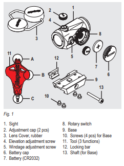
Overview (configuration)
OPERATION
WARNING: Ensure that the weapon is not loaded and that the safety selector is in the ”safe” position before attempting to install, remove or perform maintenance.
NOTE: To reach maximum protection for all weather conditions, wax is added into the rubber mixture for the
bikini lens covers. For long time storage, the wax can be seen as a grey film on the surface of the part. To
restore to its original condition, please hand wash in warm dishwater.
Install battery
- Remove the battery cap (4) using the tool (10 B).
- Insert battery (5) with positive end (+) toward battery cap (4) as can be seen in Fig. 1.
CAUTION: Check that the o-ring is in good condition and in position to ensure there is no water leakage into
the battery compartment.
- Turn to the intensity switch (6) to intensity setting 12 (max.) and tighten the battery cap (4) with the Tool (10 B). When resistance is encountered, proceed to tighten until the battery cap (4) comes to a stop.
Verify that the red dot is visible and that there is zero gap between the battery cap (4) and the battery compartment.
NOTE: For storage of the sight, remove the battery.
Install Aimpoint Micro T-1 on a weapon
If the sight is equipped with the mount shown in Fig. 1, follow the described procedure. For installation with other mounts, see accompanying instruction.
- Loosen the screw (12) using the tool (10 C), and clamp the locking bar (11) around the Picatinny rail.
- With the screw (12) (recoil stop) positioned in a groove of the Picatinny rail, push the sight forward (towards muzzle) and tighten the screw (12) using the tool (10 C)
Tighten the screw (12) until a light resistance is encountered. Proceed with another 1/4 to 1/2 turn until fully tightened (2 Nm / 1.5 ft·lb).
CAUTION: Do not overtighten.
- Proceed with zeroing (see 2.3)
Zeroing
CAUTION: Do not continue to adjust windage and elevation screws (2) and (3) if you encounter resistance.
- Remove the bikini lens cover (9).
- Adjust the intensity (6) to a comfortable intensity setting for the red dot to contrast against the target.
- Remove the adjustment caps (1) to access the windage adjustment screw (3) and the elevation adjustment screw (2). See Fig. 2.

- Use any adjustment cap (1) or the tool (10 A) to turn the adjustment screws (2) and (3). Place the knobs on the adjustment cap (1) into the recesses on the adjustment screws (2) and (3).
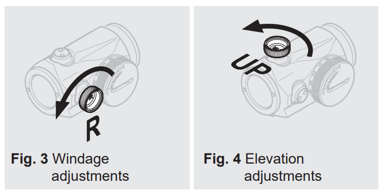
- Windage adjustments (see Fig. 3):
- Turn windage adjustment screw (3) counterclockwise to move point of impact to the right.
- Turn windage adjustment screw (3) clockwise to move point of impact to the left.
- Elevation adjustments (see Fig. 4):
- Turn elevation adjustment screw (2) counterclockwise to move point of impact up.
- Turn elevation adjustment screw (2) clockwise to move point of impact down.
NOTE: Each click of the adjustment screws corresponds to a 13 mm movement of the point of
impact at 100 m or 0.5 in at 100 yds.
- Confirm zeroing by firing at least three shots at a zeroing target. Check points of impact to confirm accuracy and repeat zeroing procedure if required.
- After initial firing, ensure the sight is securely installed on the weapon.
EXTREME CONDITIONS
- Extreme heat (moist or dry): no special procedures required.
- Extreme cold: extreme cold might shorten battery life. The intensity switch (6) can be more difficult to operate than at normal temperatures.
- Salt air: no special procedures required.
- Sea spray, water, mud, snow: ensure the battery cap (4) and the adjustment caps (1) are tightened. Tighten the adjustment caps (1) and the battery cap (4) by hand and by the use of the tool (10 B). Keep lens covers (9) on when the sight is not being used. Clean lenses and wipe the sight dry after exposure.
- Dust storms and sand storms: keep lens covers (9) on when the sight is not being used.
- High altitudes: no special procedures required.
CAUTION: Never clean the lenses with fingers. Use lens paper/cloth. If lens paper/cloth is not available:
- To clear away debris (sand, grass etc.): blow away the dirt or rinse with clear water.
- To clean lenses: fog the lenses or rinse with clear water and clean them with a soft piece of cloth.
TROUBLESHOOTING
The red dot does not appear or has disappeared
Clean contact surfaces and verify that the battery (5) is working and that it is installed correctly according to 2.1. Verify that there is zero gap between the battery cap (4) and the battery compartment (see Fig. 5). If the intensity switch (6) is defective, notify local dealer/armourer.

The sight is impossible to zero
If an adjustment screw is at its limit, check the alignment of mount and barrel. If point of impact is moving, check the stability of mount and weapon rail (or carry handle)
The front lens of the sight is tilted, has the sight been damaged?
No. The optical system is designed for the front lens to be mounted in this way.
MOUNT INSTALLATION
To avoid damage to the sight and for proper assembly of the base (7) onto the sight, the original screws (8) (M3, 4 pcs) must be tightened by hand and with the tool (10 C).
- Place the sight upside down in your hand.
- Press the base (7) against the sight and verify there is no gap.
- Apply thread locking fluid to the threads.
- Tighten the screws (8) in a crosswise pattern. Tighten each screw until a slight resistance is encountered. Proceed with another 1/4 turn until fully tightened. This is equivalent to 0.8 Nm (0.6 ft·lb) of torque.
CAUTION: Do not overtighten.