1. Scope description
1.1 Introduction
The Schmidt & Bender Polar T96 hunting scope is designed to meet the unique challenges of high precision shooting. The extremely high level of transmission enables an image of high contrast and brightness even in twighlight. Its quality and function makes it possible to achieve exceptional shooting results as well as to fulfill the critical and demanding needs of official, law enforcement and tactical applications. Strict observation of the following operating instructions is prerequisite for successful long-term use.
1.2 Safety instructions
Never look into the sun or into laser light with the scope. This may cause serious eye injuries. Do not tamper with the scope. Any repairs beyond the
maintenance described in the maintenance manual should only be
performed by Schmidt & Bender or by other specialists authorized by Schmidt & Bender. Protect the scope against shocks beyond normal use.
Avoid unnecessary long exposure of the scope to direct sunlight; intense and excessive sun radiation will cause extremely high temperatures inside the tube which may be detrimental to the scope.
The scope must be properly mounted to the firearm by a qualified specialist.
Perfect mounting is an essential requirement for maximum accuracy and
efficient functioning of the firearm and the scope. Be sure to assume the
proper firing position and keep a correct eye relief in order to obtain an
optimal full field of view and to avoid any injuries due to the recoil of the
weapon.
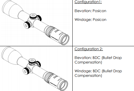
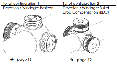
2. Configurations
This manual uses figures of version “BDC” to demonstrate the functions of the scope.
The manual can be transferred on the Posicon- configuration.
3. Technical data
3.1 General data
| Field of view Exit pupil Eye relief Twilight factor Transmission Diopter adjustment Parallax Reticle focal plane |
15,0 – 3,7 (m/100m) 12,0 – 5,0 (mm) 90 (mm) 11,2 – 22,4 96 (%) +2 to -3 (dpt) fix 100 (m) 1st or 2nd |
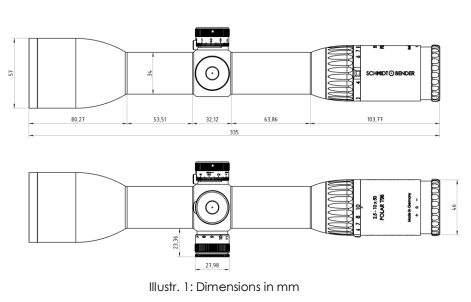
3.2 Dimensions
4. Accessories / Scope of supply
The following accessories are supplied along with the riflescope. These parts
can be ordered from a specialist dealer or our service if necessary.
Further accessories can be found on our homepage.
Protective Bikini Caps
Registration card
Reply card
5. Operating instructions
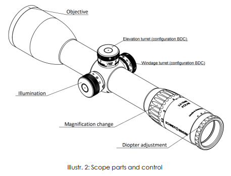
Your new Schmidt & Bender riflescope consists of different functional parts
and adjustments (See Illustr. 2).
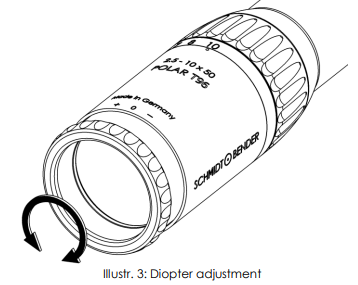
5.1 Adjusting the image focus with the diopter adjustment of the eyepiece
The eyepiece provides the adjustment of the reticle focus to the individual
eye diopter. Set the scope to the highest magnification. Rotate the eyepiece
counterclockwise until it stops. Rotate the eyepiece clockwise until you see a
sharp image of the reticle (see Illustr. 3).
5.2 Illumination Control
Your new Polar riflescope is equipped with the Flash Dot technology which
provides a projected bright red dot.
The bright red dot positioned in the center vanishes completely when
switched off.
For optimal target acquisition on dark background, set the intensity of the
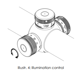
illuminated dot to the respective light conditions.
To do this the illumination control may be turned from -0- toward position -11- until a setting is achieved where the red dot is just bright enough to be picked up by the eye without glaring. If possible, this adjustment should be performed under quiet conditions prior to the actual shooting (see Illustr. 4).
If the illumination is not switched off by the shooter after use, illumination
control electronics automatically switch off the illumination after 6 hours.
If the illumination starts blinking, the battery is low and should be replaced.
5.3 Changing the battery
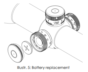
To replace the battery screw off the battery cap and remove the old battery.
Please discard the used battery in an ecologically compatible way!
Place the new battery (coin cell CR 2032/3V) with the „+” facing up into the
battery compartment. Do only change the battery in a dry environment.
Battery service life is at least 100 hours at the highest intensity (see Illustr. 5).
5.4 Using the reticle fort the distance estimation (reticle in 1st focal plane)
The different available reticles offer a variety of possibilities to estimate or
measure important parameters by means of reticle subtensions. This allows the shooter to place highly precise shots even on large distances by use of the estimates and the ballistic compensator.
The reticle is in the first focal plane such that the reticle subtensions remain
constant on all magnifications.
Exemplary for one reticle in the first focal plane (reticle L7; see Illustr. 6) the
distance “A” of the large tics corresponds to 140cm/100m. The shooter can
thus calculate the distance to a target which size is known by measuring it
with the reticle pattern: If a 140 cm sized target fits inbetween the distance
“A”, it is positioned in a distance of 100 m.
For arbitrary object sizes and distances a relation exists according to the
following formula:

Whereas
𝑑 is the distance to the target,
𝑔 is the estimated size of the target,
𝑎 is the size of the target on the reticle pattern.
According to the measured distance, the parallax can be set and the bullet
drop can be compensated by the elevation turret.
The reticle subtensions for your reticle can be found in the catalog or on the
available datasheets.
For second focal plane reticles, the coverages correspond to one magnification on which the following estimations can be performed
accordingly.
6. Preliminary adjusting and fine adjusting when sighting in
6.1 Configurations and features of the elevation- and windage-turret
The Polar T96 is available in various versions.Please refer to the table below
which version correspondents with your scope and read into the correspondenting position what opportunities the turrets are able to provide.
6.2 Using the Posicon turrets
For use of the turrets, please remove the caps from the windage and
elevation turret by unscrewing counter-clockwise (Illustr. 7).

Your new riflescope is equipped with the Posicon-windage and elevation
adjustment. On delivery, the black arrow in the white screen of the turret
indicator points onto the center, symbolized by an – o -.
This ensures that in both left-to-right and up-to-down direction the maximal
amount of adjustment range is available.
The arrow of the so called “Posicon-Clock” provides information on the
position of the reticle at any time. (Illustr. 8)
The green sector indicates the square adjustment range in which one
windage and elevation adjustment do not interfere with each other. The red
sector indicates the so called buffer, which provides an additional amount of
adjustment in either direction, but in which one adjustment direction might
interfere with the other.

When sighting in the scope for the first time, or re-sighting the scope due to
service or repair, a test shoot for zeroing the scope must be performed on a
100m distance.
The centering of the target pattern and thus zeroing of the scope is then
performed according to paragraph 6.2.1 and 6.2.2.
6.2.1 Elevation adjustment (Posicon)
The point of impact is moved by 1cm on 100m on every click. A too low point of impact is corrected by rotating the elevation turret clockwise into the direction indicated by “H” or “U” (see Illustr. 9), a too high point of impact by rotating the elevation turret counter-clockwise into the direction indicated by “T” or “D”.

6.2.2 Windage adjustment (Posicon)
The point of impact is moved by 1cm on 100m on every click. A too far left
point of impact is corrected by rotating the elevation turret clockwise into the direction indicated by “R” (Illustr. 10), a too far right point of impact by rotating the elevation turret counter-clockwise into the direction indicated by “L”.

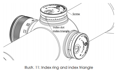
6.2.3 Marking the zero position (Posicon)
All obtained reticle positions may be marked by the aluminum ring below the knurl.
To do so, please unscrew the cross-slot screw in the Posicon screen and
position and turn the aluminum ring until the index dot and the index triangle match. Then screw the cross-slot screw tightly. (Illustr. 11)
6.3 Using the Bullet Drop Compensation (BDC)
In order to avoid the unintentional adjustment of the elevation or the windage turret, both turrets provide a locking mechanism.
To lock each of the turrets, its circumferential ring has to be turned 90°
clockwise (Illustr. 12). A little slider serves as an aid which is located left hand
side (elevation) or on top of the turret (windage).

6.3.1 Marking the zero position
When sighting in the scope for the first time, or re-sighting the scope due to
service or repair, a test shoot for zeroing the scope must be performed on a
100m distance. Therefore, ensure that the parallax is set to the correct value
of 100m and that both elevation and windage turrets are set to “0”.
The differences arising from the shot image towards the target, must now be
corrected according to the procedure described in paragraph 6.3.2 and
6.3.3.
Please verify the centered shot pattern by again firing a group of shots at the target. If necessary repeat the correction procedure.
After sighting in, the scope must be zeroed. Therefore, turn the turrets to the unlocked position and loosen the screws on the turrets with an Allen key by turning it counter-clockwise. Please do not remove the screws completely
(Illustr. 13).

Now turn the turret caps back to zero such that the zero is in line with the
engraved index dot. Then fix the screws with the Allen key.
The adjusting caps are secured by a driven-in screw, so that they cannot
be removed while zeroing. Please do not loosen this screw.
The turret clicks can still be felt and heard when the screws are unlocked.
The reticle will not be misaligned while the setscrews are loosen.
6.3.2 Elevation adjustment (BDC)
The point of impact is moved by 1cm on 100m on every click. A too low point of impact is corrected by rotating the elevation turret clockwise (see Illustr. 14), a too high point of impact by rotating the elevation turret counter-clockwise.

6.3.3 Windage adjustment (BDC)
The point of impact is moved by 1cm on 100m on every click. A too far left
point of impact is corrected by rotating the elevation turret clockwise into the direction indicated by “R” (see Illustr. 15), a too far right point of impact is corrected by rotating the turret counter-clockwise into the direction indicated by “L”.

7. Maintenance
7.1 Care and maintenance
The Schmidt & Bender Polar T96 scope does not require any special
maintenance. All metal parts have a hard anodized surface that is extremely
scratch-resistant and easy to care for.
For cleaning outer surfaces, use a clean and, if necessary, a slightly damp
cloth.
Before wiping the optic’s surfaces, use a dry brush to remove coarse dirt or
dust particles. Slight impurities may then be wiped off using a microfibre cloth.
Breathe onto the optic’s surfaces before cleaning them, this helps with the
cleaning process. Excessive dirt may be removed using lukewarm water.
Avoid dry rubbing on the outside optical surfaces, this may harm the precious coatings.
7.2 Storage temperature
The approved temperature range for the storage of the scope is from -55°C
to 70°C.
8. Warranty certificate
We hereby certify that our Quality Management System has been approved
by Unternehmensgruppe TUV Rheinland Berlin Brandenburg to the following Quality Management Standard: The TUV Cert Certification Body of TUV Anlagentechnik GmbH (Unternehmensgruppe TUV Rheinland Berlin
Brandenburg) certifies in accordance with TUV Cert procedures that Schmidt
& Bender GmbH & Co. KG, Am Grossacker 42, D- 35444 Biebertal has
established and applies a quality management system for the design,
production sales and service of fine mechanical optical instruments. Main
product telescopic sights. Proof has been furnished that the requirements
according to ISO 9001 – # Registration No. 01 100 67280 – are fulfilled. All parts have been thoroughly inspected in accordance with the afore-mentioned Quality Management System and correspond to the requirements of the specifications, drawings, test procedures and standards in all respects.
Guarantee clause:
– Guarantee period of 10 years
– Replacement parts are available for at least 30 years
Contact:
Schmidt & Bender GmbH & Co. KG • Am Grossacker 42 • D-35444 Biebertal •Germany
Tel. +49 (0) 64 09-81 15-0 • Fax +49 (0) 64 09-81 15-11
[email protected] • www.schmidt-bender.de
Schmidt & Bender Inc. • 204 McGhee Rd• Winchester, VA 22603• U.S.A.
• Phone +1(540)4508132• [email protected]