Schmidt & Bender 1.1-5×24 Stratos
1. Scope description
1.1 Introduction
The Schmidt & Bender Stratos hunting scopes are designed to meet the
unique challenges of high precision shooting. You are owning a product of
highest quality, optimized for your special applications. Strict observation of
the following operating instructions is prerequisite for successful long-term use.
1.2 Safety instructions
Never look into the sun or into laser light with the scope. This may cause serious eye injuries. Do not tamper with the scope. Any repairs beyond the
maintenance described in the maintenance manual should only be
performed by Schmidt & Bender or by other specialists authorized by Schmidt & Bender. Protect the scope against shocks beyond normal use.
Avoid unnecessary long exposure of the scope to direct sunlight; intense and
excessive sun radiation will cause extremely high temperatures inside the tube which may be detrimental to the scope.
The scope must be properly mounted to the firearm by a qualified specialist.
Perfect mounting is an essential requirement for maximum accuracy and
efficient functioning of the firearm and the scope. Be sure to assume the
proper firing position and keep a correct eye relief in order to obtain an
optimal full field of view and to avoid any injuries due to the recoil of the
weapon.
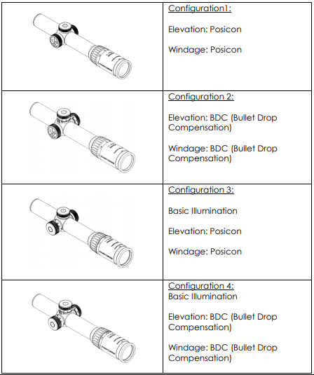
2. Configurations
This manual uses figures of version “BDC” to demonstrate the functions of the scope. The manual can be transferred on the Posicon-configuration.
3. Technical data
3.1 General data
| Field of view Exit pupil Eye relief Twilight factor Transmission Diopter adjustment Parallax Reticle focal plane |
37,6 – 7,6 (m/100m) 12,6 – 4,8 (mm) 90 (mm) 5,1 – 11 90 (%) +2 to -3 (dpt) fix 100 (m) – 2nd |
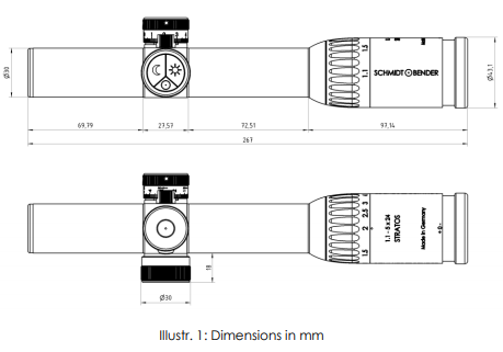
3.2 Dimensions
4. Accessories / Scope of supply
The following accessories are supplied along with the riflescope. These parts
can be ordered from a specialist dealer or our service if necessary.
Further accessories can be found on our homepage.
Protective Bikini Caps
Registration card
Reply card
5. Operating instructions
Your new Schmidt & Bender riflescope consists of different functional parts
and adjustments (See Illustr. 2).

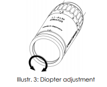
5.1 Adjusting the image focus with the diopter adjustment of the eyepiece
The eyepiece provides the adjustment of the reticle focus to the individual
eye diopter. Set the scope to the highest magnification. Rotate the eyepiece
counterclockwise until it stops. Rotate the eyepiece clockwise until you see a
sharp image of the reticle (see Illustr. 3).
5.2 The Choose-Your-Light-Illumination
All Stratos riflescopes are equipped with the Choose-Your-Light Illumination
(Illustr. 4) which provides a large quantity of different functions and which can be programmed to your individual needs at your local gunsmith or at the Schmidt & Bender service or even by yourself at home by purchasing the
optionally available USB adapter.

An overview on the various functions, possible configurations as well as on the standard configurations is given by the following tabular.
| Function | Options | Standard |
| Number of illumination settings (day) | 12/24/48/continuous | 12 |
| Number of illumination settings (night) | 12/24/48/continuous | 12 |
| Automatical continuous brightness adjustment | on / off | on |
| Brightest setting / Darkest setting | Brightness selectable | Daylight usable / Nightlight usable |
| Brightness curve | Selectable on 12/24/48 settings | logarithmic |
| Cant sensor vertical | on (light/strong) / off | On / ~ 35°-45° |
| Cant sensor horizontal | on (light/strong) / off | On / ~ 35°-45° |
| Automatic switch-off: | Time selectable | 6h |
| Low battery indicator deactivation | On / Off | Off |
| Behavior on switch-on | 3 different behaviors selectable | Behavior 3 (s. p.12) |
All Stratos riflescopes have the ultra bright FlashDot technology which
provides a perfect circular shaped red dot projected into the center of the
reticle. By switching off this dot disappears completely to provide a clear and
undisturbed view on the target. In your scope reticle and FlashDot are located in the second focal plane.
5.2.1 Number of illumination settings
The illumination unit comprises a day-mode and a night mode. Optionally, it
is possible to program the illumination unit such that only one mode is used.
Each of these modes provides a selectable number of illumination settings.
It can be chosen from 12, 24, or 48 settings or a basically continuous brightness adjustment, which has 96 settings lying indistinguishable close to each other such that the adjustment seems to be continuous for the human eye.
The standard setup has 12 illumination settings for the day-mode and 12 for
the night-mode.
5.2.2 Sequential brightness adjustment
The scopes offer an option to adjust the brightness sequentially when holding on one of the buttons. This option is activated on delivery.
5.2.3 Brightest and darkest setting and brightness curve
The brightest and darkest setting in day- and night-mode can be chosen
freely within the physically possible parameters. The brightness curve from
darkest to brightest setting can also be chosen freely for 12, 24, and 48
settings.
In case that 96 settings, equally to continuous adjustment, are chosen, the
brightness curve follows a logarithmic scale.
On delivery, the brightness adjustment range in day-mode and night-mode is defined such that all hunting situations during daytime or nighttime are
covered. The brightness curve follows a logarithmic scale.
5.2.4 Cant sensors
This riflescope provides a horizontal and a vertical cant sensor, which allows
automatic switch-off when laying or putting the weapon aside. When leveling the gun, the illumination is reactivated immediately for a precise
instantaneous shot.
Both sensors can be activated or deactivated separately. Additionally, the
sensor can be configured to react on a steep or low angle.
On delivery, both sensors are activated and configured to react on an angle
of approximately 35°-45°.
5.2.5 Automatic switch off
The illumination has an automatic switch-off function for power saving. The
illumination switches off after a selectable period of time without pressing any button.
On delivery this time is set to 6 hours.
5.2.6 Behavior on activation and reactivation
There are 3 different selectable scenarios for the behavior on activation and
reactivation:
- On activation or reactivation the illumination returns to the lastly used
brightness setting in the particular mode. - On activation or reactivation the illumination goes to one concrete
but selectable setting in the particular mode. - On activation or reactivation the illumination returns for a selectable
time period to the lastly used brightness setting and returns after
expiration of this time period to a certain selectable setting in each mode.
On delivery the third option is chosen.
For 12 hours the illumination returns to the lastly used setting in each mode,
and after 12 hours it returns to the medium setting in each mode.
5.2.7 Deactivation of the low-battery warning
If the remaining battery power decreases below a certain level, the
illumination starts to blink.
This blinking can be deactivated by switching off the illumination and
reactivating it within 2 seconds. Afterwards, the illumination can be used until the battery is empty.
Of course, on decreasing battery power, the illumination brightness will
decrease accordingly.
5.3 Illumination control
The Choose-Your-Light-Illumination has three buttons with engraved symbols in terms of a sun, a moon and a Schmidt & Bender logo.
These buttons provide different functions as explained in the following.
5.3.1 Switching the illumination on and off (standard)
- To activate the illumination in its day-mode, press the button with
the sun. - To activate the illumination in its night-mode, press the button with
the moon. - To switch off the illumination, press the button with the Schmidt &
Bender logo for 3 seconds. - When reactivating within 12 hours after the last use, the illumination
returns into the lastly chosen setting in each mode. - After 6 hours the illumination switches off automatically.
- To change from day-mode to night-mode or from night-mode to
day-mode the illumination must be switched off and reactivated in
the respective mode.

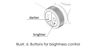
5.3.2 Adjusting the brightness
- To increase the brightness of the flash dot, press the button with the
sun. Each keystroke increases the brightness by one level. When holding the button, the brightness can be increased sequentially. - To decrease the brightness of the flash dot, press the button with the
sun. Each keystroke decreases the brightness by one level. When holding the button, the brightness can be decreased sequentially.
This is valid for both the day-mode and the night-mode.
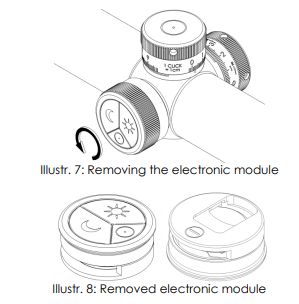
5.4 Battery change
To change the battery the inner electronic module must be removed by
turning the outer flange counter-clockwise until no resistance can be felt
anymore (Illustr. 7).
You can easily take out the module afterwards.
Now, push the battery with your thumb into the direction of the “-“-sign on the back of the module, such that it sticks out of the slot and can be pulled out (Illustr. 9). (In the windage cap of the scope you can find a spare CR 2032
battery which can be used as a replacement).

Please discard the used battery in an ecologically compatible way!
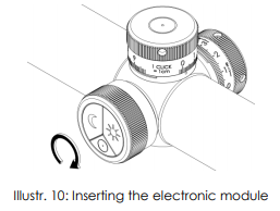
Push the new battery into the slot of the electronic module. Please watch for
the correct orientation of the battery: The positive pole of the battery (usually signed with a „+“) should point towards the buttons of the module.
Then place the electronic module into the guiding flange and turn clockwise
until the block (Illustr. 10).
Please do only change the battery in a dry environment and use only
batteries of type CR 2032/3V.
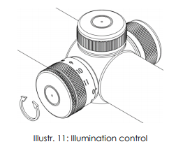
5.5 Illumination control (basic)
Your new riflescope is equipped with the Flash Dot technology which provides a projected bright red dot along with a reticle in the second focal plane.
The bright red dot positioned in the center of the reticle vanishes completely
when switched off.
For optimal target acquisition on dark background, set the intensity of the
illuminated dot to the respective light conditions.
To do this the illumination control may be turned from -0- toward position -11- until a setting is achieved where the red dot is just bright enough to be picked up by the eye without glaring. If possible, this adjustment should be performed under quiet conditions prior to the actual shooting (see Illustr. 11).
If the illumination is not switched off by the shooter after use, illumination
control electronics automatically switch off the illumination after 6 hours.
If the illumination starts blinking, the battery is low and should be replaced.
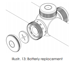
5.6 Changing the battery (basic)
To replace the battery screw off the battery cap and remove the old battery.
Please discard the used battery in an ecologically compatible way!
Place the new battery (coin cell CR 2032/3V) with the „+” facing up into the
battery compartment. Do only change the battery in a dry environment.
Battery service life is at least 100 hours at the highest intensity (see Illustr. 12).
6. Preliminary adjusting and fine adjusting when sighting in
6.1 Configurations and features of the elevation- and windage-turret
The 1.1-5×24 Stratos is available in various versions. Please refer to the table
below which version correspondents with your scope and read into the
correspondenting position what opportunities the turrets are able to provide.

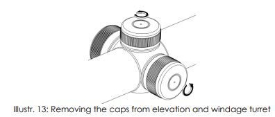
6.2 Using the Posicon turrets
For use of the turrets, please remove the caps from the windage and
elevation turret by unscrewing counter-clockwise (Abb. 13).
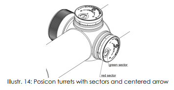
Your new riflescope is equipped with the Posicon-windage and elevation
adjustment. On delivery, the black arrow in the white screen of the turret
indicator points onto the center, symbolized by an – o -.
This ensures that in both left-to-right and up-to-down direction the maximal
amount of adjustment range is available.
The arrow of the so called “Posicon-Clock” provides information on the
position of the reticle at any time. (Abb. 14)
The green sector indicates the square adjustment range in which one windage and elevation adjustment do not interfere with each other. The red
sector indicates the so called buffer, which provides an additional amount of
adjustment in either direction, but in which one adjustment direction might
interfere with the other.
When sighting in the scope for the first time, or re-sighting the scope due to
service or repair, a test shoot for zeroing the scope must be performed on a
100m distance.
The centering of the target pattern and thus zeroing of the scope is then
performed according to paragraph 6.2.1 and 6.2.2.
6.2.1 Elevation adjustment (Posicon)
The point of impact is moved by 1cm on 100m on every click. A too low point of impact is corrected by rotating the elevation turret clockwise into the direction indicated by “H” or “U” (see Abb. 15), a too high point of impact by rotating the elevation turret counter-clockwise into the direction indicated by “T” or “D”.

6.2.2 Windage adjustment (Posicon)
The point of impact is moved by 1cm on 100m on every click. A too far left
point of impact is corrected by rotating the elevation turret clockwise into the direction indicated by “R” (Illustr. 16), a too far right point of impact by rotating the elevation turret counter-clockwise into the direction indicated by “L”.

6.2.3 Marking the zero position (Posicon)
All obtained reticle positions may be marked by the aluminum ring below the knurl.
To do so, please unscrew the cross-slot screw in the Posicon screen and
position and turn the aluminum ring until the index dot and the index triangle match. Then screw the cross-slot screw tightly. (Illustr. 17)

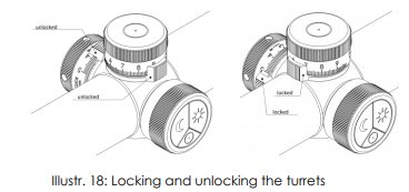
6.3 Using the Bullet Drop Compensation (BDC)
In order to avoid the unintentional adjustment of the elevation or the windage turret, both turrets provide a locking mechanism (Illustr. 18).
To lock each of the turrets, its circumferential ring has to be turned 90°
clockwise. A little slider serves as an aid which is located left hand side
(elevation) or on top of the turret (windage).
6.3.1 Marking the zero position (BDC)
When sighting in the scope for the first time, or re-sighting the scope due to
service or repair, a test shoot for zeroing the scope must be performed on a
100m distance. Therefore, ensure that the parallax is set to the correct value
of 100m and that both elevation and windage turrets are set to “0”.
The differences arising from the shot image towards the target, must now be
corrected according to the procedure described in paragraph 0 and 6.3.3.
Please verify the centered shot pattern by again firing a group of shots at the
target. If necessary repeat the correction procedure.
After sighting in, the scope must be zeroed. Therefore, turn the turrets to the
unlocked position and loosen the screws on the turrets with an Allen key by
turning it counter-clockwise. Please do not remove the screws completely
(see Illustr. 19: Zeroing of the turrets).
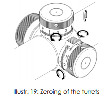
Now turn the turret caps back to zero such that the zero is in line with the
engraved index dot. Then fix the screws with the Allen key.
The reticle will not be misaligned while the setscrews are loosen. Now the Allen screws must be tightened.
The adjusting caps are secured by a driven-in screw, so that they cannot
be removed while zeroing. Please do not loosen this screw.
The turret clicks can still be felt and heard when the screws are unlocked.
The reticle will not be misaligned while the setscrews are loosen.
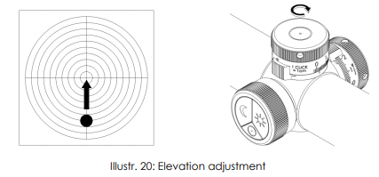
6.3.2 Elevation adjustment (BDC)
The point of impact is, depending on the configuration, moved by 1cm on
100m or ¼ MOA on every click. A too low point of impact is corrected by
rotating the elevation turret clockwise (see Illustr. 20: Elevation adjustment), a too high point of impact by rotating the elevation turret counter-clockwise.
6.3.3 Windage adjustment (BDC)
The point of impact is, depending on the configuration, moved by 1cm on
100m or ¼ MOA on every click. A too far left point of impact is corrected by
rotating the elevation turret clockwise into the direction indicated by “R” (see
Illustr. 21: Windage adjustment), a too high point of impact by rotating the
elevation turret counter-clockwise into the direction indicated by “L”.

7. Maintenance
7.1 Care and maintenance
Schmidt & Bender Stratos line scopes do not require any special maintenance. All metal parts have a hard anodized surface that is extremely
scratch-resistant and easy to care for.
For cleaning outer surfaces, use a clean and, if necessary, a slightly damp
cloth.
Before wiping the optic’s surfaces, use a dry brush to remove coarse dirt or
dust particles. Slight impurities may then be wiped off using a microfibre cloth.
Breathe onto the optic’s surfaces before cleaning them, this helps with the
cleaning process. Excessive dirt may be removed using lukewarm water.
Avoid dry rubbing on the outside optical surfaces, this may harm the precious coatings.
7.2 Storage temperature
The approved temperature range for the storage of the scope is from -55°C
to 70°C.
8. Warranty certificate
We hereby certify that our Quality Management System has been approved
by Unternehmensgruppe TUV Rheinland Berlin Brandenburg to the following
Quality Management Standard: The TUV Cert Certification Body of TUV
Anlagentechnik GmbH (Unternehmensgruppe TUV Rheinland Berlin
Brandenburg) certifies in accordance with TUV Cert procedures that Schmidt
& Bender GmbH & Co. KG, Am Grossacker 42, D- 35444 Biebertal has
established and applies a quality management system for the design,
production sales and service of fine mechanical optical instruments. Main
product telescopic sights. Proof has been furnished that the requirements
according to ISO 9001 – # Registration No. 01 100 67280 – are fulfilled. All parts have been thoroughly inspected in accordance with the afore-mentioned Quality Management System and correspond to the requirements of the specifications, drawings, test procedures and standards in all respects.
Guarantee clause:
– Guarantee period of 10 years
– Replacement parts are available for at least 30 years
Contact:
Schmidt & Bender GmbH & Co. KG • Am Grossacker 42 • D-35444 Biebertal •
Germany
Tel. +49 (0) 64 09-81 15-0 • Fax +49 (0) 64 09-81 15-11
[email protected] • www.schmidt-bender.de
Schmidt & Bender Inc. • 204 McGhee Rd• Winchester, VA 22603• U.S.A.
• Phone +1(540)4508132• [email protected]