Products:
PLEASE read instructions before operating or installing this sighting system.

PACKAGE CONTENTS
Models – SL, CSL (Polymer Bodies)
Qty 1 – Instruction Manual
Qty 1 – Serendipity Mounting Instructions
Qty 1 – Serendipity Red Dot Sight
Qty 1 – Hardware Pack = (1) Hex Wrench 1/16, (1) Hex Wrench 5/64, (2) Extra Cover Screws,
Qty 1 – Mounting Screw Pack = (8) Mounting Screws 5-40 x .330” (6 required, 2 extra)
INTENSITY SWITCHES
C-MORE sighting systems are available with two switch styles, standard and click adjustable. The standard is a dial rheostat switch with a continuous adjustment through the wide intensity range. The click adjustable switch has 12 positions. The first position is off and the second and third are for night vision (low / high) and are not visible. Positions 4 – 12 are the visible intensity settings giving you a wide range of adjustment for any lighting condition.
INTENSITY ADJUSTMENT
The intensity of the dot needs to be adjusted to the lighting condition in the operating area. The dot should appear bright but not glaring. For example, outside in bright sunlight you will most likely use the brightest setting, while at dawn or dusk, or indoors you will need to use one of the lower settings. The first two positions on the click switch are extremely dim and can only be seen through a Night Vision device.
INSTALLATION
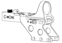
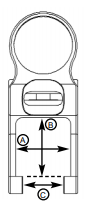
The Serendipity was originally designed to attach to 1911 style handguns for competition shooting by drilling and tapping the frame and mounting the sight directly via the integral mount. The mounting legs allow for a maximum slide width of .950” (A). The mounting legs allow for a maximum slide height of 1” (B). The mounting pads can be machined to accomodate frame widths
between .750” and 1” (C).
Proceed to the Serendipity Mounting Instructions sheet included with this Instruction Manual to continue the installation process.
ZEROING
STOP! Before sighting in, read and follow ALL manufacturer’s precautions and safety instructions for handling your firearm. BE SAFE! Know the NRA’s rules for safe gun handling.
ADJUSTMENT NOTES:
- The windage and elevation adjustment screws both have locking screws which must be loosened before the sight can be adjusted. Failure to do so could result in damage to the sight.
- The adjustment screws are extremely sensitive, especially the elevation screw. You will only need to turn them slightly to change your point of impact.
- The adjustment screws are tight to turn. This is normal. Make sure to use a screwdriver that fits the slot correctly and make sure the locking screws are loose before attempting to make adjustments.
- Elevation: Clockwise moves point of impact up.
- Windage: Clockwise moves point of impact right.
- Remember to loosen the locking screws before making an adjustment and lock the locking screws after each adjustment.
- When making final adjustments, tune the elevation first and lock it down, then repeat for the windage.
ZEROING PROCEDURE:
- Turn the sight on and adjust the brightness to suit the lighting condition.
- Shoot a 3 shot group at a target 10 yards away to get on paper.
- Loosen the locking screws and adjust the windage and elevation so your group is centered and 2 to 3 inches low.
- Since the sight can only be zeroed for one distance, zero for the farthest distance you will shoot with this firearm.
- Shoot a 3 shot group at the final distance you determined in step 4.
- Adjust the windage and elevation until zero is achieved.
MAINTENANCE
The sight does not require any special maintenance other than keeping it clean and making sure everything is tight. Doing the following after each shooting session, will ensure the sight a long life.
- Clean the sight. Use a soft clean cloth to wipe down the sight body (Not the Lens) and remove powder residue.
- Clean the lens. The hard coated glass lens is very durable, but periodic cleaning is necessary. Use a clean gauze, facial or lens tissue and any commercial glass cleaner or soap and water. Dust, dirt and powder residue can be very abrasive, so a thorough rinsing before wiping will help to protect from scratching while cleaning.
- Clean the diode. Powder residue will build up around the hole were the light is emitted. This can make the dot appear distorted. The best way to combat this is to blow off the face of the diode with compressed air after shooting. You can use canned air for cleaning computer keyboards.
- Check the mounting. Check to make sure the sight is mounted securely. DO NOT OVERTIGHTEN!
- Check the locking screws. Check to make sure the locking screws are tight. DO NOT OVERTIGHTEN!
- Check the Guide Pin. The Guide Pin is next to the Elevation Lock Screw on the right side of the sight. It is not an adjustment scew. The Windage Block slides on this pin when windage adjustments are made. The pin simply screws in until tight. Make sure it has not loosened and tighten if necessary. DO NOT OVERTIGHTEN!
BATTERY REPLACEMENT
The 3 volt lithium battery (Duracell DL1/3N or Energizer 2L76) is located in the battery compartment on the top of the sight. You will need to remove the battery cover which is the larger of the covers. Using the hex wrench provided, remove the two flat head hex screws and the cover. Place the hex wrench in the groove in the front side of the battery compartment to elevate the battery and facilitate its removal. Make sure the orange rubber shims behind the battery contacts don’t fall out. Note the polarity of the battery and install the new one with the same orientation (negative to left). Replace the battery cover and reinstall screws. DO NOT OVERTIGHTEN!
DIODE MODULE REPLACEMENT
Diode Modules are available in 6 different sizes and are color coded on the bottom of each module:
2 moa (red), 4 moa (green), 6 moa (blue), 8 moa (yellow), 12 moa (orange), 16 moa (purple).
REMOVAL
You will need to remove the diode cover which is the smaller of the two covers on the top of the sight. Using the hex wrench provided, remove the two flat head hex screws and the cover. It may be helpful to remove the battery cover as well. Using a pair of pliers, grasp the diode module on the sides and pull straight up. This will unplug the module from its socket. You may want to use a cloth on the diode module before grasping to prevent scratching.
INSTALLATION
With the diode module facing the lens, insert the module into its socket paying special attention that the 8 pins on the module align with the 8 sockets. Push the module straight down until the retaining shelf is flush with the top of the sight surface. Replace the diode cover and reinstall the screws. DO NOT OVERTIGHTEN! Moderately snug is sufficient. It will be necessary to check your zero and fine tune if needed.
WARRANTY
This product is warranted against original defects in material and/or manufacturing for one year. This warranty is void if the unit has been abused, disassembled, or modified/tampered with in any way from its original configuration. This warranty does not apply to defects caused by normal wear and tear, improper handling, incorrect installation, accidents, alterations/modifications to the original configuration, repairs made by unauthorized parties, aftermarket accessories, or abnormal use. Due to the fragile nature of glass, the lens is specifically excluded from warranty coverage.
This warranty is limited to the original purchaser and is not transferable.
Pat. No. 5,369,888 Pat. No. 5,383,278 Other U.S. & Foreign Patents Pending.