Products:
PACKAGE CONTENTS:
- 1 – STS2 Sight
- 2 – Direct Mounting Screws
- 1 – Cover
- 1 – Wrench – Mounting Screws
- 1 – Instruction Manual
- 1 – Adjustment Wrench

DESCRIPTION OF MAJOR COMPONENTS
INTENSITY SWITCH
Used to set the intensity (Brightness) of the dot or turn the dot off. The STS2 provides 10 visible brightness settings.
Turning ON: Pressing either the up or down button will turn the dot on to the previously set intesity.
Adjusting: Pressing the UP button will adjust the intensity of the dot UP incrementally to position 10. Pressing the DOWN button will adjust the intensity of the dot DOWN incrementally to position 1.
Turning OFF: Holding either button for 3 seconds will turn the dot off.
Auto OFF: The dot will turn OFF automatically after 8 hours of inactivity.
LOCK SCREW
Used to lock the elevation and windage adjustment mechanism once the sight has been zeroed to the weapon. Turning the lock screw counter-clockwise one and a half turns will loosen the screw and allow elevation and windage adjustments to be made. Turning the lock screw clockwise until firmly snug will lock the elevation and windage adjustments in their current location.
ELEVATION ADJUSTMENT SCREW
Used when zeroing weapon. Turning the elevation adjustment screw clockwise moves the point of impact down. Turning the elevation adjustment screw counter-clockwise moves the point of impact up. (1 click = 1moa)
WINDAGE ADJUSTMENT SCREW
Used when zeroing weapon. Turning the windage adjustment screw clockwise moves the point of impact right. Turning the windage adjustment screw counter-clockwise moves the point of impact left. (1 click = 1moa)
STOP! Make sure your firearm is unloaded and the magazine and ammunition has been removed before proceeding!
INSTALLATION INSTRUCTIONS
The STS2 can be installed using a C-MORE STS mount or mounting kit, or it can be installed directly to an aftermarket or custom mount using the screws provided.
C-MORE STS mount or mounting kit installation instructions:
Follow the instructions provided with the mount or mounting kit.
Direct Mounting installation instructions:
Follow the instructions provided with the mount or mounting kit, or utilize the direct mounting screws provided.
NOTE: Do Not Overtighten Mounting Screws! If the battery tray cannot be removed / installed freely, then the mounting screws are too tight causing the battery tray to bind.
Mounting Maintenance:
Periodically check the sight to ensure that it is firmly mounted and there is no movement. If movement is detected, or mounting screws have loosened, remove the mounting screws and re-apply loctite prior to re-installation.
Firing a weapon with a loose sight can cause damage to the weapon, the sight, and you!
ZEROING
NOTE: The RTS Sight has an adjustment area of 120 in. wide x 180 in. tall at 100 yds (304.8 cm x 457.2 cm at 100 m).
WARNING: The lock screw MUST be loosened before adjusting the elevation or windage screws. Failure to do so could result in damage to the adjustment mechanism. The lock screw MUST be locked (tightened) before firing.
ZEROING PROCEDURE
- Remove the sight cover.
- Turn the sight on so the dot is visible.
- Make sure the locking screw is locked before firing.
- Shoot a 3 shot group at a target 10 yards away to get on paper.
- Loosen the locking screw by turning it counter clockwise one and a half turns.
- To adjust the elevation, insert the adjustment wrench into the elevation screw. To raise the point of impact, turn the elevation screw counter-clockwise. To lower the point of impact, turn the elevation screw clockwise. (1 click = 1moa)
- To adjust the windage, insert the adjustment wrench into the windage screw. To move the point of impact left, turn the windage screw counter-clockwise. To move the point of impact right, turn the windage screw clockwise. (1 click = 1moa)
- Adjust the windage and elevation so your group is centered and 2 to 3 inches low @ 10 yards, Locking the lock screw prior to firing and loosening the lock screw prior to adjusting.
- Since the sight can only be zeroed for one distance, zero for the farthest distance you will shoot with this firearm.
- Shoot a 3 shot group at the final distance you determined in step 9.
- Adjust the windage and elevation until zero is achieved. Lock the locking screw.
- If zeroing is accurate, fire three more shots to confirm. If zeroing is not accurate, repeat steps 10 and 11 until zeroing is complete.
NOTE: After initial firing, check to ensure that the mount and sight are secure. Tighten as necessary and check periodicaly (See Maintenance Procedures)
MAINTENANCE PROCEDURES
The STS2 sight requires very little maintenance. Periodic cleaning of the lens and sight is encouraged, as well as checking the sight mounting to ensure that it is firmly mounted.
CAUTION The lens can be scratched if dirt is wiped across the lens with a cloth.
SIGHT CLEANING PROCEDURE
The STS2 sight can be cleaned using a soft cloth.
LENS CLEANING PROCEDURE
- Remove large particles from exposed lens surfaces by first blowing on the surfaces. Blow as much dust and dirt as possible from the exposed lens surfaces using compressed air.
- When all visible particles of dust and dirt have been removed, moisten a piece of lens tissue with lens cleaning solution, then gently wipe over the lens surface. Dry with clean lens tissue.
NOTE: If the lens fogs over in cold weather, use a lens tissue to wipe clear.
MOUNTING CHECK PROCEDURE
Periodically check the sight to ensure that it is firmly mounted and there is no movement. If movement is detected, or mounting screws have loosened, remove the mounting screws and re-apply loctite prior to re-installation.
Firing a weapon with a loose sight can cause damage to the weapon, the sight, and you!
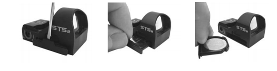
BATTERY REPLACEMENT
- Remove the sight cover.
- Remove the battery tray by using a small screwdriver to pry it open from the sight body. Ease the tip of the screwdriver behind the tab on the battery tray. Push the tip all the way down to the base of the tab and pry the tray open and pull it out of the sight. (Make sure to hold your hand over the tray to catch it when it releases from the sight)
- Insert battery into the battery tray with positive (+) side facing up.
- Insert the battery tray with battery into the sight body until it detents into the fully inserted position. (The battery tray should be flush with the side of the sight body)
WARRANTY INFORMATION
This product is warranted against original defects in material and/or manufacturing for one year. This warranty is void if the unit has been abused, disassembled, or modified/tampered with in any way from its original configuration. This warranty does not apply to defects caused by normal wear and tear, improper handling, incorrect installation, accidents, alterations/modifications to the original configuration, repairs made by unauthorized parties, aftermarket accessories, or abnormal use. Due to the fragile nature of glass, the lens is specifically excluded from warranty coverage. This warranty is limited to the original purchaser and is not transferable.